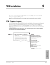
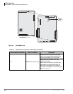
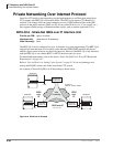
PCB Installation
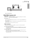
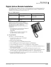
BVPU – Internet Protocol (IP) Interface Unit
Strata CTX I&M 06/04 6-15
PCB Installation
BVPU – Internet Protocol (IP) Interface Unit
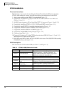
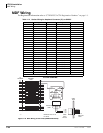
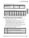
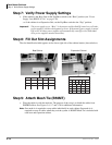
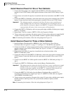
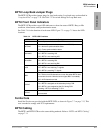
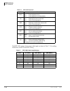
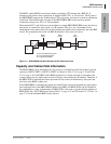
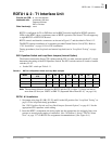
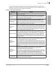
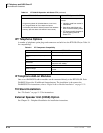
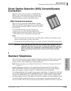
Circuits per PCB:
four Tie line circuits; one 10BaseT Ethernet connection
Interfaces with:
H.323 version 2 terminals over an IP network
Appears as:
4 E&M Tie lines
2- or 4-wire transmission
Type I and II Signaling
Immediate and Wink Start
Older Version(s):
none
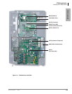
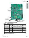
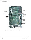
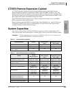
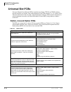
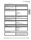
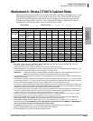
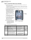
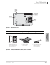
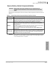
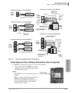
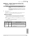
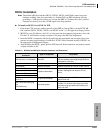
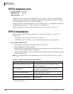
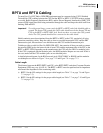
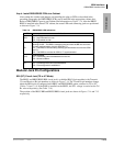
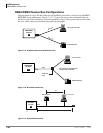
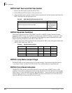
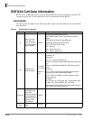
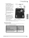
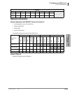
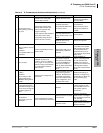
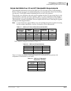
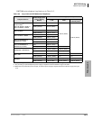
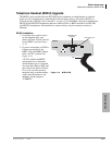
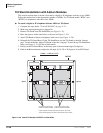
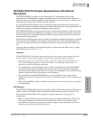
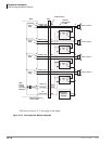
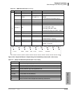
BVPU Configuration
Note Maximum of five BVPUs for CTX670 and a maximum of two BVPUs for CTX100 because
of FCC Part 15 Electromagnetic Capability (EMC) emissions restrictions.
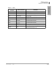
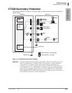
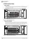
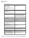
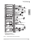
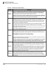
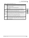
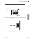
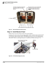
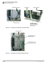
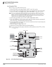
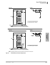
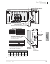
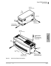
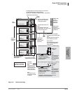
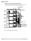
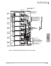
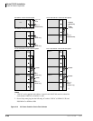
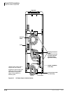
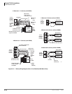
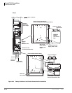
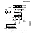
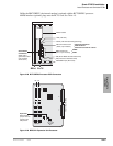
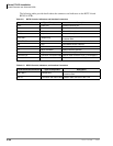
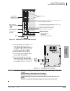
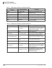
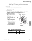
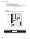
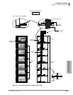
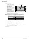
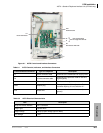
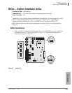
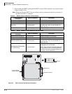
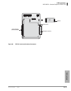
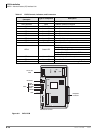
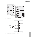
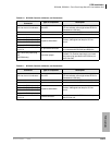
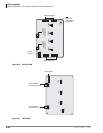
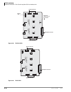
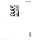
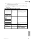
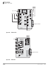
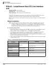
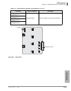
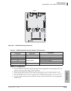
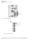
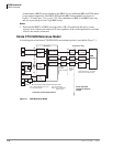
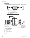
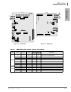
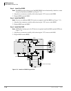
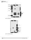
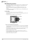
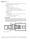
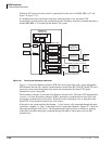
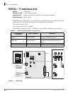
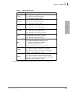
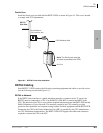
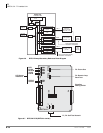
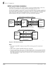
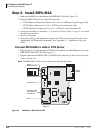
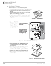
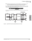
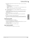
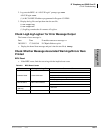
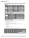
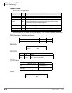
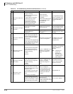
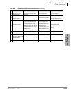
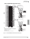
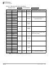
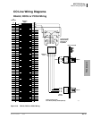
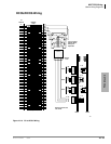
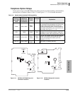
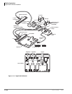
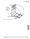
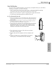
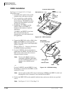
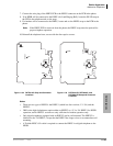
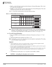
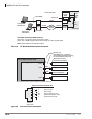
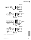
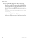
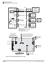
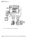
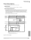
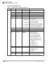
BVPU controls, indicators, and interface connectors are shown in Figure 6-10 and described in
Table 6-7.
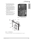
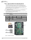
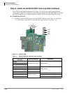
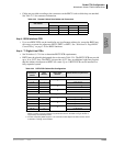
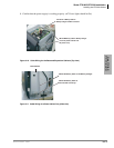
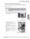
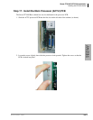
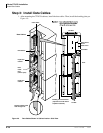
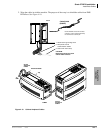
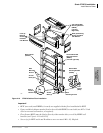
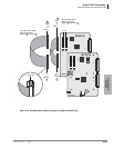
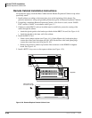
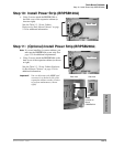
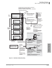
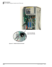
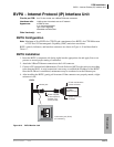
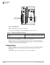
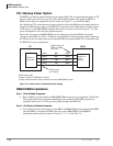
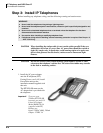
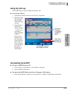
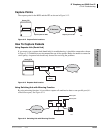
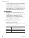
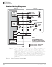
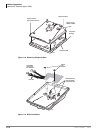
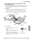
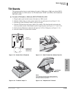
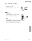
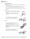
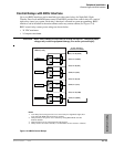
BVPU Installation
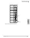
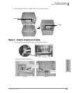
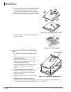
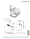
1. Insert the BVPU (component side facing right) into the appropriate slot and apply firm, even
pressure to ensure proper mating of connectors.
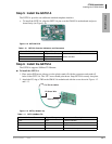
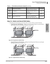
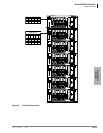
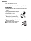
2. Attach the 10BaseT Ethernet connection to the LAN connector.
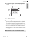
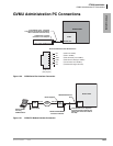
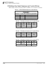
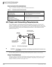
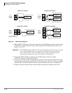
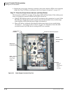
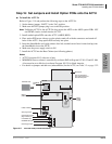
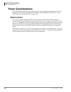
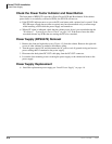
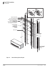
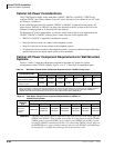
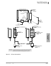
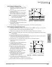
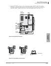
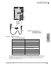
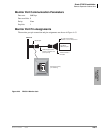
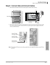
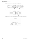
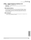
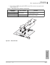
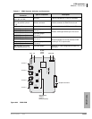
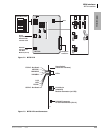
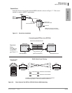
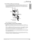
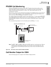
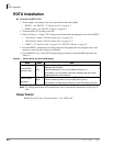
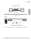
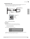
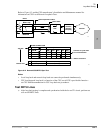
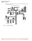
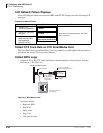
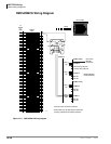
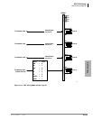
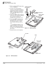
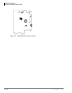
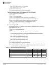
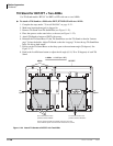
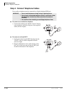
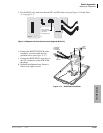
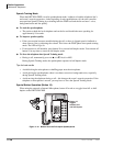
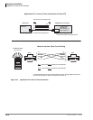
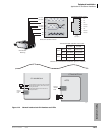
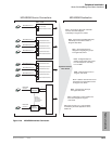
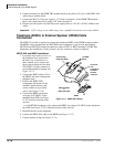
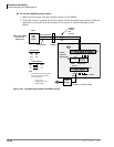
3. Connect a PC equipped with Maintenance Console Software (MCS) to the serial port according
to the drawing below. A serial connection is necessary to establish the IP address of the BVPU.
Once the IP address is established, maintenance may be conducted over the Ethernet port.
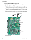
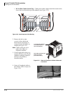
4. After installing the BVPU, gently pull it outward. If the connectors are properly mated, a slight
resistance is felt.
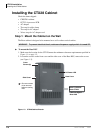
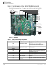
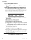
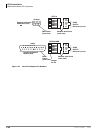
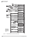
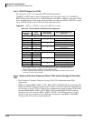
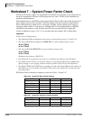
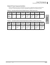
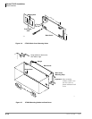
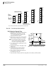
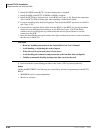
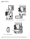
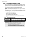
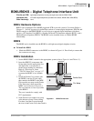
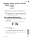
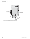
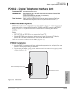
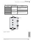
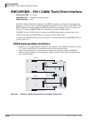
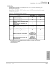
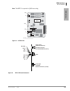
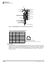
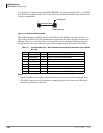
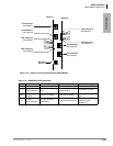
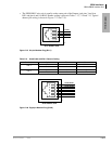
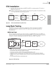
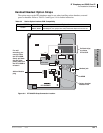
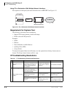
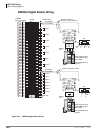
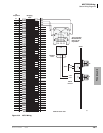
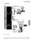
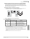
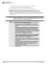
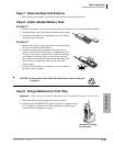
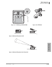
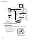
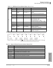
Figure 6-10 BVPU Monitor Jack
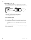
RD
TD
DSR
DTR
DCD
SG
1
2
3
4
5
6
Call-monitor jack (RJ12)
pin numbering
Dealer-supplied
6-wire telephone
modular cord
(cross-pinned)
Monitor jack
PC with maintenance
console software
PC DB9 or
DB25 Com port
Toshiba PPTC9 or
PPTC25F
BVPU
5243