


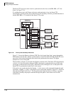
ISDN Interfaces
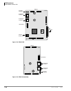
RBUU/RBUS Interface Unit
7-32 Strata CTX I&M 06/04
Notes
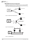
● PS2 and PS3 are not used with the Strata CTX BRI-U interface PCBs.
● Check with the BRI circuit supplier to determine the pin out of the demarc jacks because some
jacks may be wired with two or three BRI-U line circuits each jack.
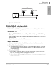
Station-Side Cabling
• The ISDN BRI U-interface circuits are two-wire on the Strata CTX station-side.
• The maximum distance between the Strata CTX ISDN BRI-U, station-side circuit (LT) and the
U-type Terminal Equipment or Terminal Adapter is 18kft.
• The house wiring from the Strata CTX BRI circuit to the wall jack should be made with CAT3~
CAT5 twisted pair wire.
• Each station-side BRI circuit requires a ferrite core as shown in Figure 7-16 on page 7-23.
• The flat satin telephone cord that connects from the wall jacks to ISDN terminal equipment
should be no longer than 33 feet.
• BRI station-side cables should not be shielded.
• Polarity of the U interface pair is not critical.
• The U interface pair should go directly from the Strata CTX interface PCB to the U-type TE1
or TA with no bridge taps or loading coils to different locations.
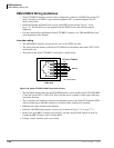
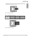
• The pin-out of the RBUU/RBUS BRI jack is shown in Figure 7-25:
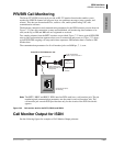
Call Monitor Jack Cabling
The pin-out for the BRI-U interface call monitor jack is provided in Figure 7-32 of this chapter.
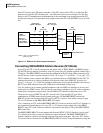
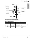
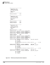
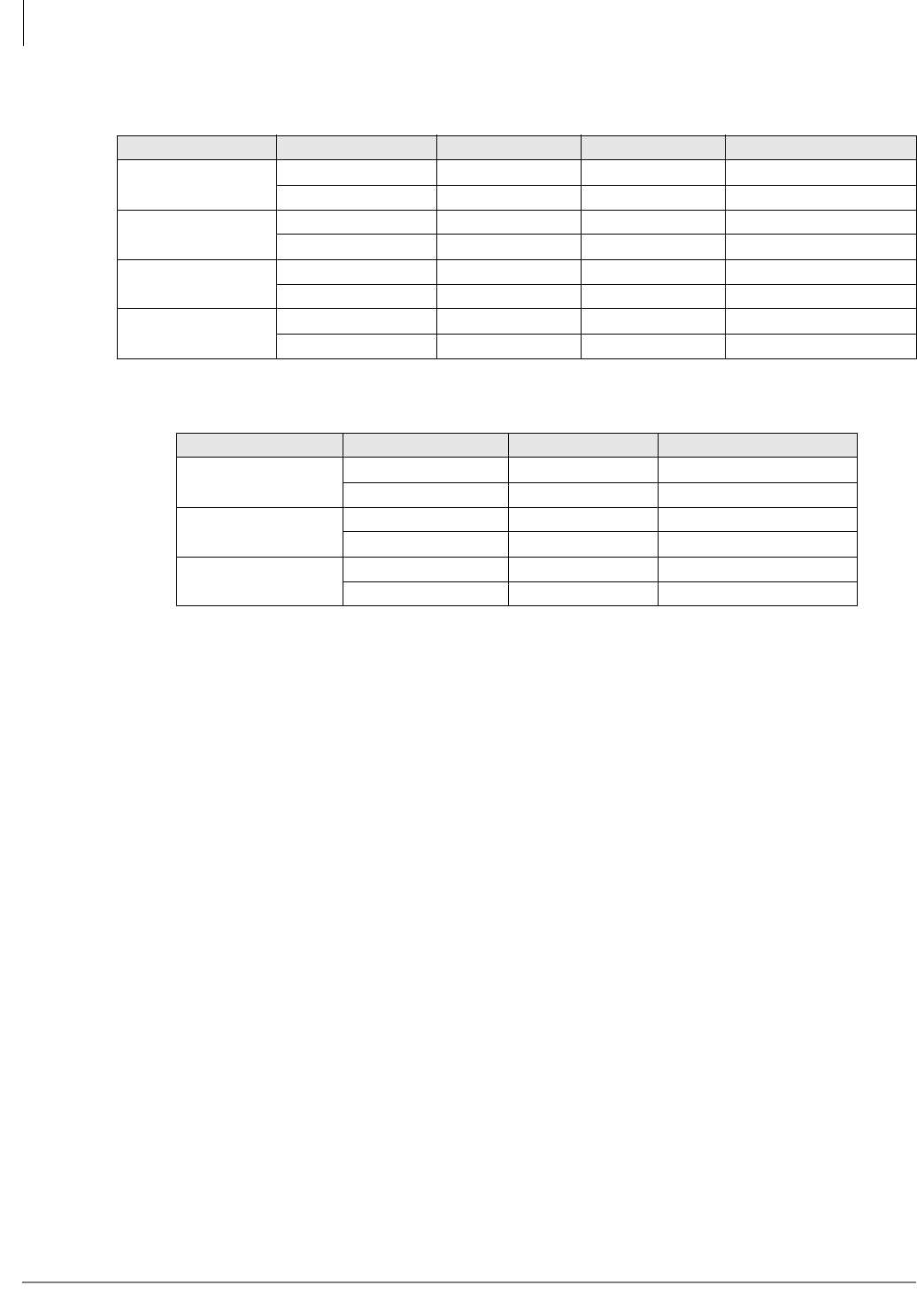
Table 7-14 Four-Pair with RJ45 Demarc Jack Coding
Conductor Color T56A Pin T56B Pin Use
Pair 1
White-Blue 5 5 Line 1
Blue 4 4 Line 1
Pair 2
White-Orange 3 1 Line 2
Orange 6 2 Line 2
Pair3
White-Green 1 3 PS3 plus power
Green 2 6 PS3 minus power
Pair 4
White-Brown 7 7 PS2 plus power
Brown 8 8 PS2 minus power
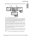
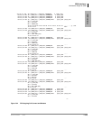
Table 7-15 Three-Pair with RJ11 Demarc Coding
Conductor Color Pin Use
Pair 1
White-Blue 4 Line 1
Blue 3 Line 1
Pair 2
White-Orange 2 Line 2
Orange 5 Line 2
Pair3
White-Green 1 Line 3
Green 6 Line 3