


PCB Installation
BDKU/BDKS – Digital Telephone Interface Unit
Strata CTX I&M 06/04 6-7
PCB Installation
BDKU/BDKS – Digital Telephone Interface Unit
Circuits per PCB:
eight digital telephone circuits (plus eight more with the BDKS PCB)
Interfaces with:
all Toshiba digital telephones (corded and cordless, DDCB, DSS, ADM, BPCI)
Older Version(s):
none
BDKU Hardware Options
BDKU can be equipped with a BDKS piggyback PCB to provide a total of 16 circuits. Refer to
Chapter 11 – Station Apparatus for instructions on how to connect digital telephones, DDCBs, and
DDSS consoles to the BDKU/BDKS, as well as how to upgrade digital telephones with these
options: a PC Interface Unit (BPCI), a Speaker Off-hook Call Announce upgrade (BVSU), and a
Headset/External Speaker (BHEU). The BDKU can be installed alone, or with the BDKS
subassembly.
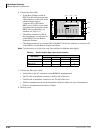
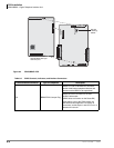
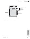
BDKS
The BDKS can be installed onto the BDKU to add eight more digital telephone circuits.
³ To install the BDKS
³ Match the BDKS connectors to the BDKU, as shown in Figure 6-4. Press firmly to ensure that
the connectors are snug.
BDKU Installation
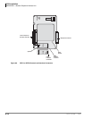
1. Set the BDKU/PDKU switch for the appropriate system (refer to Figure 6-4 and Table 6-3).
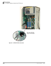
2. Insert the BDKU2 (component side
facing right) into the appropriate slot,
and apply firm, even pressure to
ensure proper mating of connectors.
Refer to “Worksheet 6: Strata
CTX670 Cabinet Slots” on page 2-37
to ensure the BDKU is in a suitable
slot.
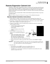
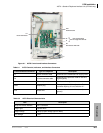
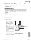
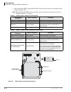
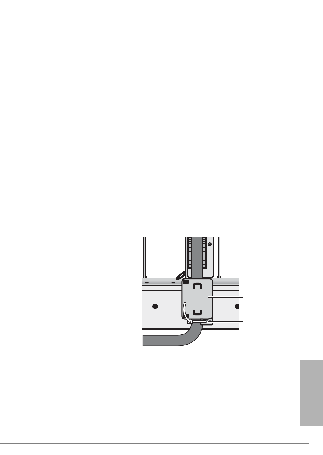
3. Install the Ferrite Core (comes with
the BDKU) onto the 25-pair cable
that connects the BDKU to the MDF:
Flip open the two snaps on the Ferrite
Core, then snap it shut around the
BDKU cord as shown in Figure 6-3.
The core must be as close as possible
to the BDKU.
The core is needed to comply with
FCC requirements.
4. Some Ferrite Cores require a tie-wrap
at the bottom to keep it from sliding.
For those, feed the tie-wrap through
the slots in the Ferrite Core, then cinch it.
S
104
5845
F
e
rr
i
t
e
C
o
r
e
T
i
e
W
r
a
p
Figure 6-3 BDKU Ferrite Core