CTX28 Installation
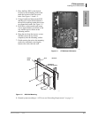
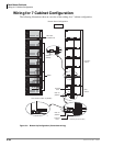
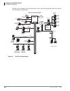
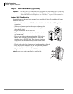
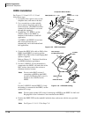
Installing the CTX28 Cabinet
1-16 Strata CTX I&M 06/04
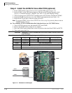
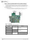
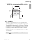
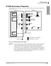
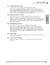
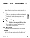
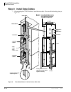
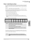
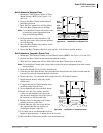
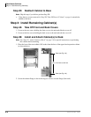
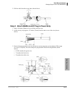
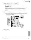
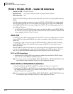
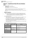
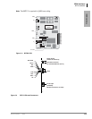
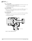
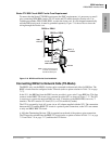
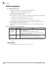
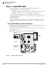
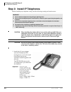
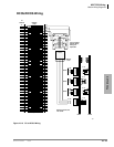
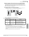
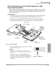
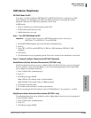
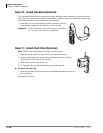
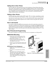
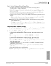
Step 4: Install the GCDU1A (DKT and Loop Start Interface)
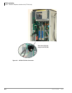
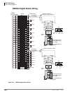
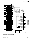
The GCDU1A PCB adds an additional 3 CO lines, 3 Caller ID units, and 8 digital telephone
circuits with a single PCB. It attaches to the GMAU1A motherboard. With the GCDU1A installed,
the CTX28 supports up to 16 digital telephones (DKTs), 6 CO lines and 6 Caller ID circuits.
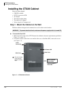
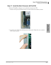
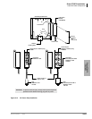
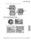
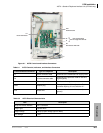
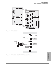
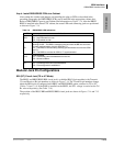
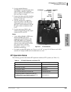
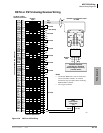
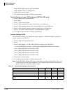
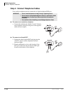
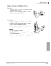
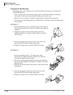
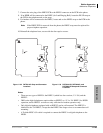
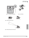
³ To install the GCDU1A
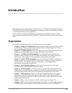
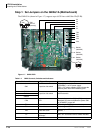
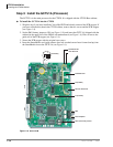
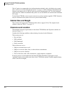
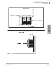
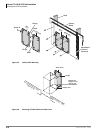
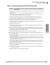
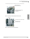
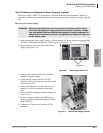
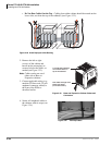
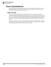
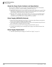
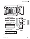
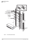
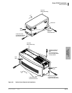
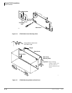
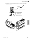
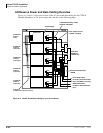
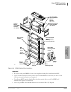
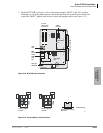
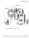
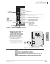
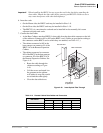
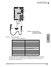
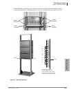
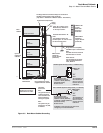
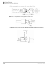
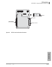
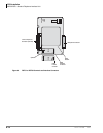
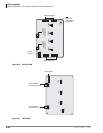
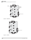
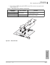
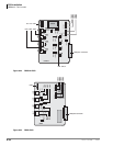
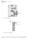
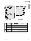
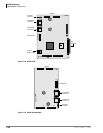
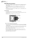
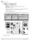
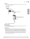
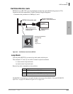
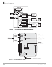
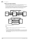
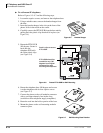
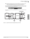
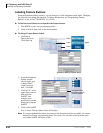
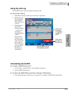
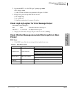
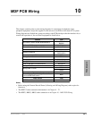
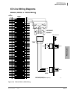
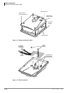
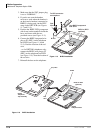
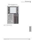
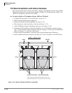
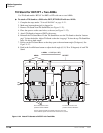
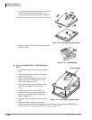
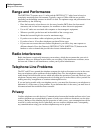
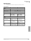
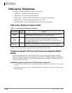
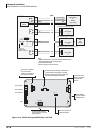
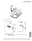
³ Carefully place the GCDU1A pins over the GMAU connectors (see Figure 1-6 and Figure
1-11). Press down on the PCB to secure the pins to the connectors (see Table 1-9).
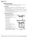
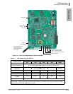
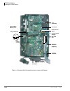
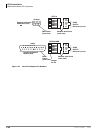
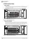
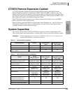
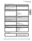
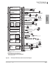
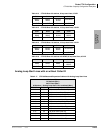
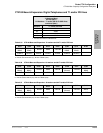
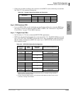
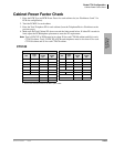
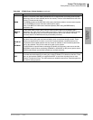
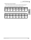
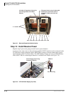
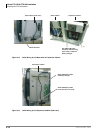
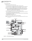
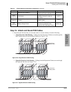
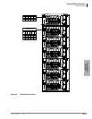
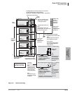
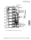
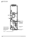
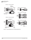
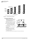
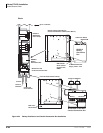
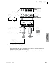
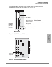
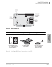
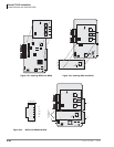
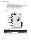
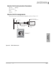
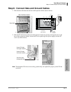
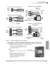
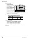
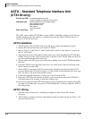
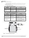
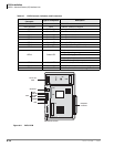
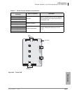
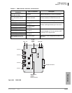
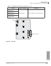
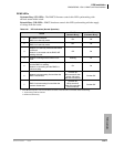
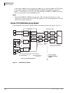
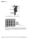
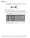
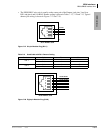
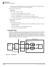
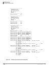
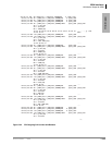
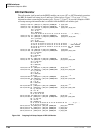
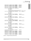
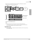
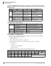
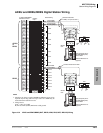
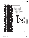
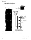
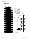
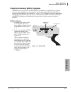
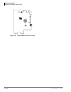
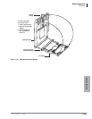
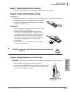
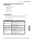
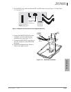
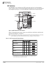
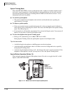
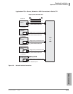
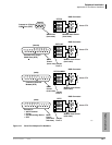
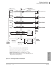
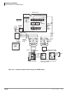
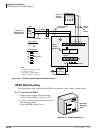
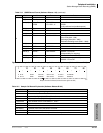
Figure 1-11 GCDU1A PCB
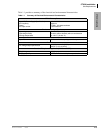
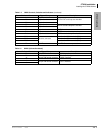
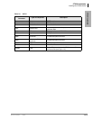
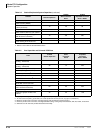
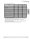
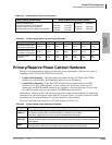
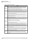
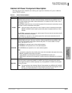
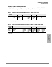
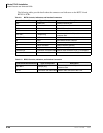
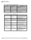
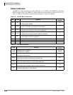
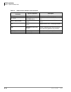
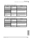
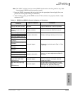
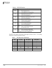
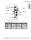
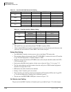
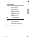
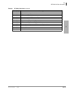
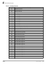
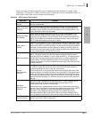
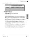
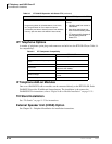
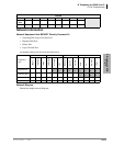
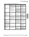
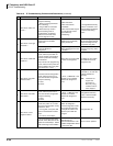
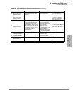
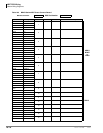
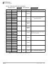
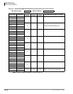
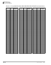
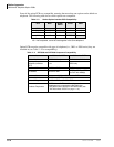
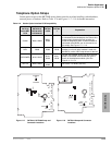
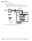
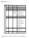
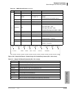
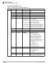
Table 1-9 GCDU1A Controls, Indicators and Connectors
Control/Indicator/
Connector
Type of Component Description
SW400
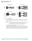
2-position slide switch 3dB Pad switchSW500
SW600
P4 16-pin male connector
GMAU interface
P5 12-pin male connector
P6 9-pin male connector
P9 6-pin male connector
P400
Modular connector
Interface for CO Line circuit (CO4)
P500 Interface for CO Line circuit (CO5)
P600 Interface for CO Line circuit (CO6)
7260
CO4
CO5
CO6
SW600
SW500
SW400