


Strata CTX
Configuration
Strata CTX Configuration
Worksheet 6: Strata CTX670 Cabinet Slots
Strata CTX I&M 06/04 2-37
Worksheet 6: Strata CTX670 Cabinet Slots
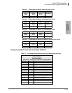
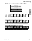
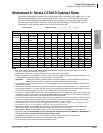
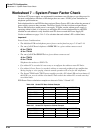
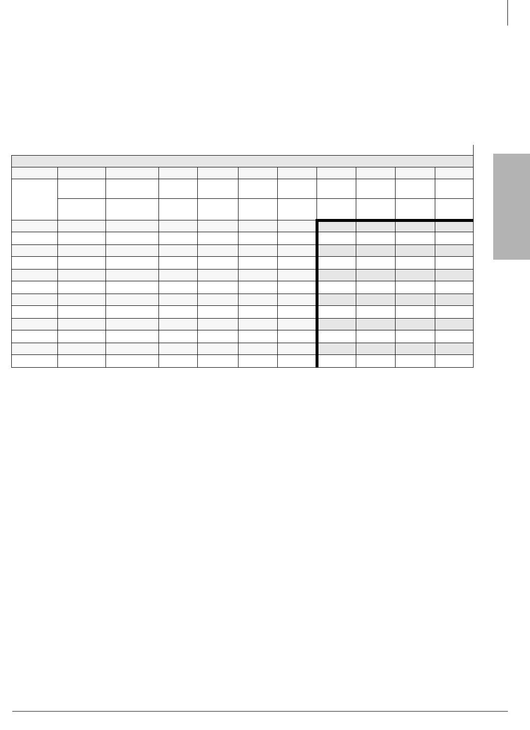
The cabinet diagram below enables you to write in the PCBs installed in each cabinet slot. Use the
PCB placement guideline below to place PCBs in the correct slots. Fill in the PCBs that go into
each slot from the PCB quantities determined in the worksheets on the previous pages and the
information provided in this worksheet. After completing Worksheet 6, Worksheet 7 must be
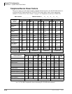
completed to verify that the cabinet power factors do not exceed 85.
Notes
● B101/B102 – Main processor slots. AMDS, BEXS, BBMS, BSIS are optional subassembly PCBs (see “CTX100
Processor Optional Subassemblies” on page 2-3).
● Cabinet slots marked with
*
provide 8 time slots; all other slots provide 16 time slots.
● BIPU-M and BIPU-Q can be installed in slots with 16 time slots only. Slots that provide 8 time slots (marked with
*
) do
not support BIPU cards. BIPU PCBs can only be placed in 16 channel slots.
Important!
If a BIPU-M or BIPU-Q is installed RCOU1A, RCOS1A RDDU1A, RGLU1A, RGLU2A, and two-wire
REMU cards should not be installed to avoid excessive Echo Return Loss (ERL).
● Any combination of up to 96 (basic processor) or 264 (expanded processor) RPTU, BPTU and RDTU channels can be
installed in the CTX670.
● RDTU, BPTU and RPTU PCBs can only be placed in odd slots of the Base Cabinet and slots S_01, S_03, and S_05 in
any Expansion Cabinet. If 17 or more channels are used, the next highest slot adjacent to the RDTU, BPTU, or RPTU
slot
cannot
be used. Slots adjacent to 8 or 16 channel RDTU, BPTU or RPTU PCBs can be used.
● The maximum number of RDTU and/or RPTU cards is determined by the CTX system line capacity. Any number of line
interface cards (RDTU, RPTU, BPTU, RCOU/RCOS, REMU, RDDU, RGLU, BIPU-Q1A) can be installed, providing that
the quantity of lines and channels do not exceed the CTX system’s line capacity.
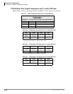
● If only 16 B channels of PRI are needed, another card can be installed in the next slot. The position of D-channels can
still be set to the 24th channel because the data of the D-channel is passed through the data highway, not the PCM
highway. The position of the D-channel doesn’t affect the installation of cards in the CTX.
● Network clock signals can only be derived from digital trunk PCBs, such as the RDTU and RPTU, that are installed in the Base
Cabinet (Master) location. Do not install these digital trunk cards into the Remote Cabinets.
● BDKU, PDKU, RDSU without Speaker OCA can be in any available slot in any cabinet. BDKU, PDKU, RDSU with
Speaker OCA can be in any available slots in the Base and S_01~S_06 in all Exp. Cabs.
● BDKU/BDKS or BWDKU without Speaker OCA can be in any available slots in the Base and S_01~S_06 in the
Expansion Cabs. It is recommended you not install Speaker OCA telephones on the BWDKU or BDKU/BDKS. If
you do, it must be in an odd slot and the next slot must be vacant.
● If the BWDKU is placed in slots 7~10, it must be set for 8 circuits with PCB jumper and in Program 100.
● Maximum 80 digital telephones per shelf due to the Power Factor restriction.
● For more details, see the following Placement Guidelines section.
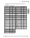
Main Location _______________ Remote Location 1___ 2___ 3___ 4___ 5___ 6___
CTX Cabinet Slots
Base B101 B102 S101 S102 S103 S104 S105 S106 S107 S108
PCB Type
BEXU
BCTU
(AMDS, BSIS)
BECU
(BEXS, BSIS)
BBCU
(BBMS)
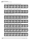
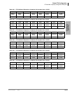
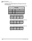
Cab 2 S201 S202 S203 S204 S205 S206 S207* S208* S209* S210*
PCB Type
Cab 3 S301 S302 S303 S304 S305 S306 S307* S308* S309* S310*
PCB Type
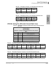
Cab 4 S401 S402 S403 S404 S405 S406 S407* S408* S409* S410*
PCB Type
Cab 5 S501 S502 S503 S504 S505 S506 S507* S508* S509* S510*
PCB Type
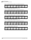
Cab 6 S601 S602 S603 S604 S605 S606 S607* S608* S609* S610*
PCB Type
Cab 7 S701 S702 S703 S704 S705 S706 S707* S708* S709* S710*
PCB Type