


CTX28 Installation
Installing the CTX28 Cabinet
Strata CTX I&M 06/04 1-17
CTX28 Installation
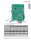
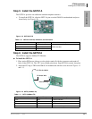
Step 5: Install the GSTU1A
The GSTU1A provides one additional standard telephone interface.
³ To install the GSTU1A, align the GSTU1A pins over the GMAU1A motherboard and press
down firmly (see Figure 1-6).
Figure 1-12 GSTU1A PCB
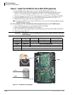
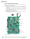
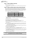
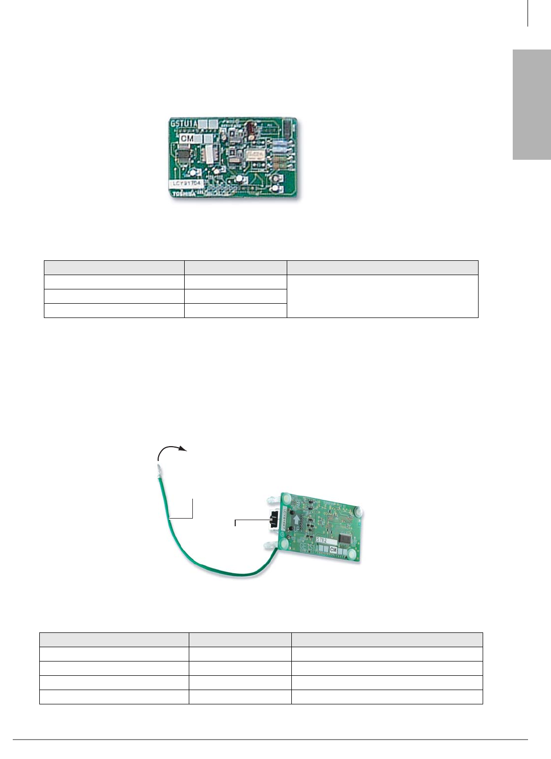
Step 6: Install the GETS1A
The GETS1A supports 100Base TX Ethernet.
³ To install the GETS1A
1. Place option PCB arrow side up over the plastic stand-off with the connectors and stand-off
holes on the GCTU1A. The “UP” arrow should point down. Snap GETS1A securely into place.
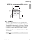
2. Attach the FG ring to TB2 on the GMAU1A motherboard with the screw shown in Figures 1-2
and 1-13.
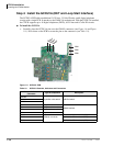
Figure 1-13 GETS (100Base TX)
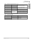
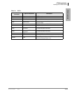
Table 1-10 GSTU1A Controls, Indicators, and Connectors
Control/Indicator/Connector Type of Component Description
P7 12-pin male connector
GMAU interfaceP8 9-pin male connector
P11 3-pin male connector
Table 1-11 GETS (100Base TX)
Control/Indicator/Connector Type of Component Description
CD1 LED LAN link indicator
CD2 LED Transmission and receive indicator
P1 60 pin connector GCTU interface
P2 RJ45 Network interface port
7259
7261a
Ethernet Plug
FG Green Wire
To TB2 On GMAU