


Rack Mount Cabinets
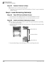
Step 7: Verify Power Supply Settings
5-12 Strata CTX I&M 06/04
Step 7: Verify Power Supply Settings
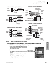
³ If the cabinet is the Base Unit set the Exp/Base switch to the “Base” position (see “Power
Supply Unit (BRPSU672A)” on page 5-28).
...or if the cabinet is an Expansion Unit, set the Exp/Base switch to the “Exp” position.
Important! The power supply set as “Base” is the master and has On/Off control over all other
power supplies, which are designated as slaves. If the master power supply is turned
Off or On, all other power supplies will automatically turn Off or On. (Individual
slave power supplies must be turned On.)
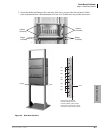
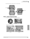
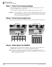
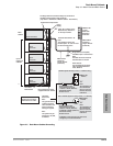
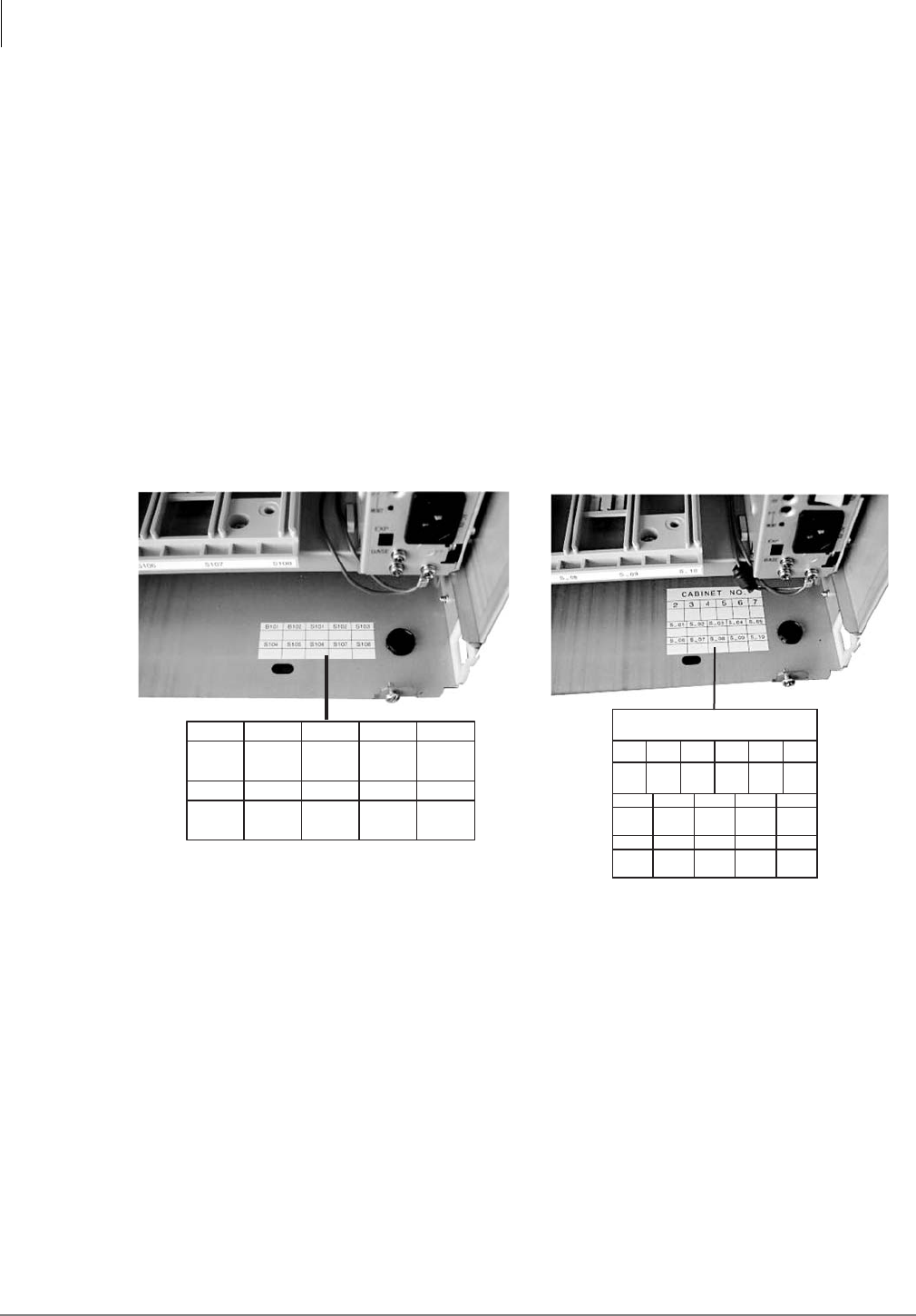
Step 8: Fill Out Slot Assignments
The slot identification label appears on the lower right side of the cabinet interior (shown below).
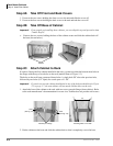
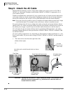
Step 9: Attach Mesh Tie (B50MT)
³ Wrap the cables in with the mesh tie. The purpose of the wrap is to shield the cables from
EMI/RFI effects. See Figures 5-6, 5-7 and 3-10 for additional information.
Note One mesh tie is required to wrap cables individually in each cabinet. One mesh tie is
required to wrap all cables where they exit the system. A B50MT Mesh Tie is included with
each base and expansion cabinet.
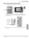
6999
B101 B102 S101 S102 S103
S104 S105 S106 S107
S108
Base Cabinet
6998
CABINET NO.
2
S_01 S_02 S_03 S_04 S_05
S_06 S_07 S_08 S_09 S_10
34567
Expansion Cabinet