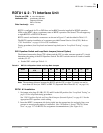
T1
RDTU1 & 2 - T1 Interface Unit
8-16 Strata CTX I&M 06/04
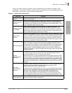
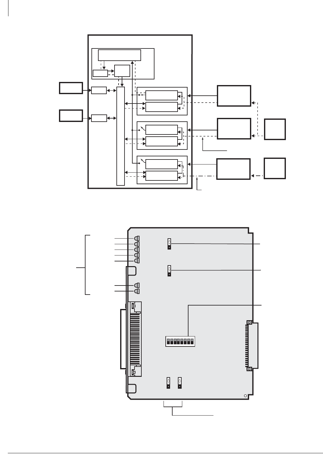
Figure 8-7 RDTU1A PCB (RDTU2 is similar)
5439
PDKU
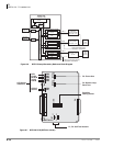
Primary Reference PCB*
Secondary Reference PCB*
Other RDTU, RPTU, or RBSU
CTX Digital Transmission Voice Path
Synchronization
Circuit
Synchronization
Circuit
Synchronization
Circuit
Digital Voice
Path
Digital Voice
Path
Digital Voice
Path
Strata CTX
Digital
Telephone
Standard
Telephone
SS
1
SS
2
SS
3
Line 1
Line 2
Line 3
Public Switched
Telephone
Network (PSTN)
PRI, BRI, or T1
AT&T or
other provider
PRI, BRI, or T1
Other
PRI, BRI, or T1
provider
Stratum-1
Clock
Source
Processor PCB
Clock not synchronized properly
with Stratum-1 Clock Source
Time
Switch
Clock
Synchronization
Circuit
Clock synchronized properly
with Stratum-1 Clock Source
Other
Clock
Source
RSTU
Figure 8-6 RDTU Primary/Secondary Reference Block Diagram
P3: Future Use
P4: Remote Loop
Back Test
Equalizer
Setting Switch
P1, P2: Self Test Network
CD3
CD7
CD6
CD5
CD4
BSY
FLAM
MFALM
YALM
BALM
CD2
CD1
PSYNC
SSYNC
6396
P1
P6
OFF ON
P2
LB
OFF
S1 OFF S8
ON
P3LLB
OFF ON
P4RLB
OFF ON
LED Status
Indicators
SW1
RDTU1A


