


Strata CTX670 Installation
Mount Cabinets
Strata CTX I&M 06/04 4-11
Strata CTX670
Installation
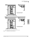
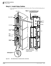
Wall Mounting Expansion Cabinets
1. Remove the front, back, and side covers from the Expansion Cabinets.
Note The two screws on the front cover and the two screws on each side cover should be
loosened just enough to slide the covers off. The front cover slides left and the side covers
swing out and down for removal.
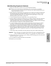
2. Hold an Expansion Cabinet back cover against the wall so that its top locating parts align with
the bottom locating parts of the Base Cabinet back cover (see Figure 4-4 on page 4-12). To
secure the Expansion Cabinet back cover to the back board, repeat Steps 5~11 from “Wall
Mounting the Base (Top) Cabinet” on page 4-10.
3. To install additional Expansion Cabinet back covers, repeat Step 2 above.
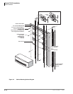
4. Starting with the top Expansion Cabinet back cover (which is fastened to the wall), position an
Expansion Cabinet on the back cover cabinet hangers. Slide the cabinet to the right to the
proper mounting position, and secure the cabinet to the back cover with two screws to the right
side of the back cover. Repeat for all other Expansion Cabinets.
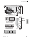
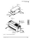
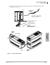
5. Loosen the bonding connection plates fastened on both sides of the first Expansion Cabinet
(see Figure 4-9) then fasten the plates between the Base Cabinet and the first Expansion
Cabinet. Repeat to connect the first Expansion Cabinet to the second Expansion Cabinet, etc.
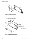
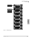
6. Base Cabinet: Loosen data cable door locking screws and open data cable doors; then connect
the first Expansion Cabinet data cable to the “CAB 2” (top) data cable connector on the Base
Cabinet. Install data cables in appropriate connectors for all other Expansion Cabinets. (See
Figure 4-12.
7. After all data cables are installed, close data cable doors and secure with the locking screw.
Important! Data cable door screws must be firmly tightened for proper system operation. Data
cables for DK280 and DK424 cabinets are not compatible with CTX670 cabinets.
8. Install ground wiring, AC and reserve power cabling, and PCB cabling per the “Recommended
Installation Sequence” on page 4-6.
9. Fill out cabinet/slot identification labels on each cabinet.
10. Reinstall covers onto cabinets.