


ISDN Interfaces
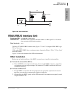
RBSU/RBSS Interface Units
Strata CTX I&M 06/04 7-25
ISDN Interfaces
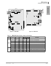
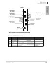
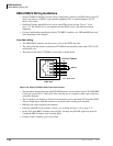
modular connectors, as explained in previous paragraphs, maintains control of polarity. The pinout
from the RBSU/RBSS circuit to a S-type TE-1 or TA device is shown in Figure 7-18 and Table
7-10.
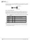
Figure 7-18 RBSU/RBSS NT Circuit Pinout on Passive Bus
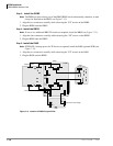
As a parallel bus, the RBSU/RBSS BRI-NT passive bus will accept TE-1 and TA devices scattered
on the bus; however, the locations of the TE and TA devices on the S bus is limited by timing
considerations. Specifically, the round trip propagation delay of a signal from the RBSU/RBSS
circuit to one device must be within four microseconds of the delay from the other device on the
bus. That is to say, layer-1 frames from the RBSU/RBSS must be received within a two
microsecond window. This says nothing about how large the delay can be. In fact, it can be much
larger, as long as the differences remain small.
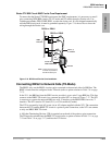
To control electrical characteristics, a 100-ohm terminating resistor (TR) is required at both ends
of the passive bus. One resistor should be across the Tx pair and one across the Rx pair at either
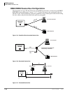
end of the passive bus. Branch-type passive bus configurations, shown in Figures 7-19~7-22, may
only require a TR on the RBSU/RBSS NT circuit side and not on the TE or TA device side of the
bus.
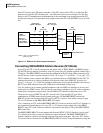
The RBSU and RBSS circuits provide an option switch that allows the 100-ohm TR to be switched
into the circuit on the Strata CTX side of the bus (see Table 7-8 on page 7-17 and Table 7-11 on
page 7-22). Most TE-1 and TA devices also provide option switches to connect 100-ohm
terminating resistors as shown in Figure 7-17.
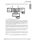
If the TE or TA devices do not provide TRs, they may be permanently wired in place on a RJ45
jack at the far end of the bus. Only one terminating resistor on each pair should be on the far (TE)
end of the passive bus - do not switch in TRs on more than one TE-1 or TA device on the passive
bus.
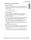
Important! The correct placement of TRs on the Passive Bus is critical to ISDN BRI circuit
operation (see the following RBSU/RBSS Passive Bus configurations section).
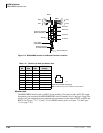
RBSU
NT Circuit
Insert 100-ohm
TR using RBSU
and RBSS
option switches.
RJ45
Pinout
5434
S-type, TE-1s or TAs without
100-ohm terminating resistors
(maximum eight TE-1s or TAs per
RBSU/RBSS circuit).
BRI (four-wire)
3
6
4
5
3
6
4
5
RJ45
Pinout
S-type, TE-1 or TA with
100-ohm TR or just a
100-ohm terminating
resistor across each pair
on a RJ45 jack.
To local
AC Power
To local
AC Power
3 6 4 5