


ISDN Interfaces
RBSU/RBSS Interface Units
7-20 Strata CTX I&M 06/04
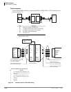
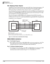
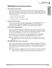
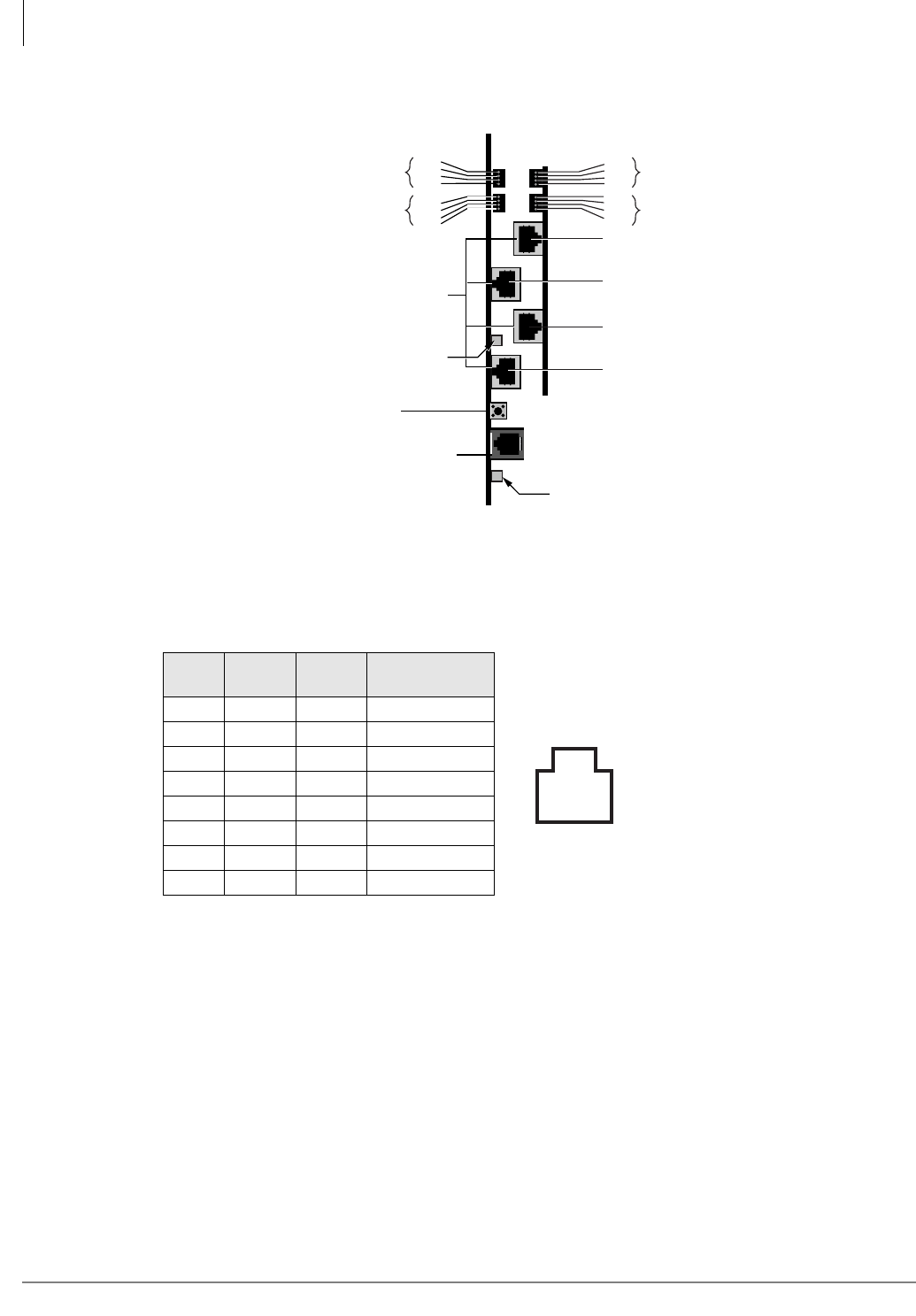
Figure 7-14 RBSU/RBSS Location of LEDs and Connector Locations
Monitor Jack
The RBSU/RBSS monitor jack is an RJ12 (6-pin modular). This jack provides an RS-232 output
that enables you to monitor the RBSU/RBSS BRI circuit D-channel, layer-2 and layer-3 data. The
monitor jack pin configuration and communication parameters are the same as BPTU or RPTU and
RBUU (see Figures 7-32, 7-35 and 7-36). For RBSU monitor jacks, see Figure 7-34 and Figure
7-14 on page 7-20.)
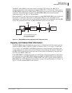
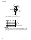
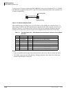
Table 7-10 RJ45 Pins in the 8-pin Modular Jack
Pin
No.
TE
Side
NT
Side
PS1/R40S
Polarity
1 N/C N/C N/C
2 N/C N/C N/C
3TxRx +
4RxTx +
5RxTx -
6TxRx -
7 N/C N/C N/C
8 N/C N/C N/C
RBSU
Reset Switch
(resets RBSU Firmware)
RS-232C Connector
for Call-Data Monitor
RJ-45 8-pin (shielded)
Modular Connector
BSY
TS
LOS
FS
BSY
TS
LOS
FS
2795
RBSS
3rd Circuit
2nd Circuit
1st Circuit
4th Circuit
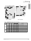
BSY
TS
LOS
FS
BSY
TS
LOS
FS
CKT2
CKT1
CKT4
CKT3
TB3 (FG)
TB1 and TB2 (PFT)
87654321
3048
Front View of RJ-45 Jack Cavity
Note: The RJ-45 pins are numbered as shown above.