


Strata CTX Configuration
Functional Block Diagrams
2-18 Strata CTX I&M 06/04
Functional Block Diagrams
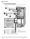
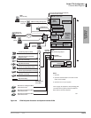
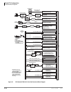
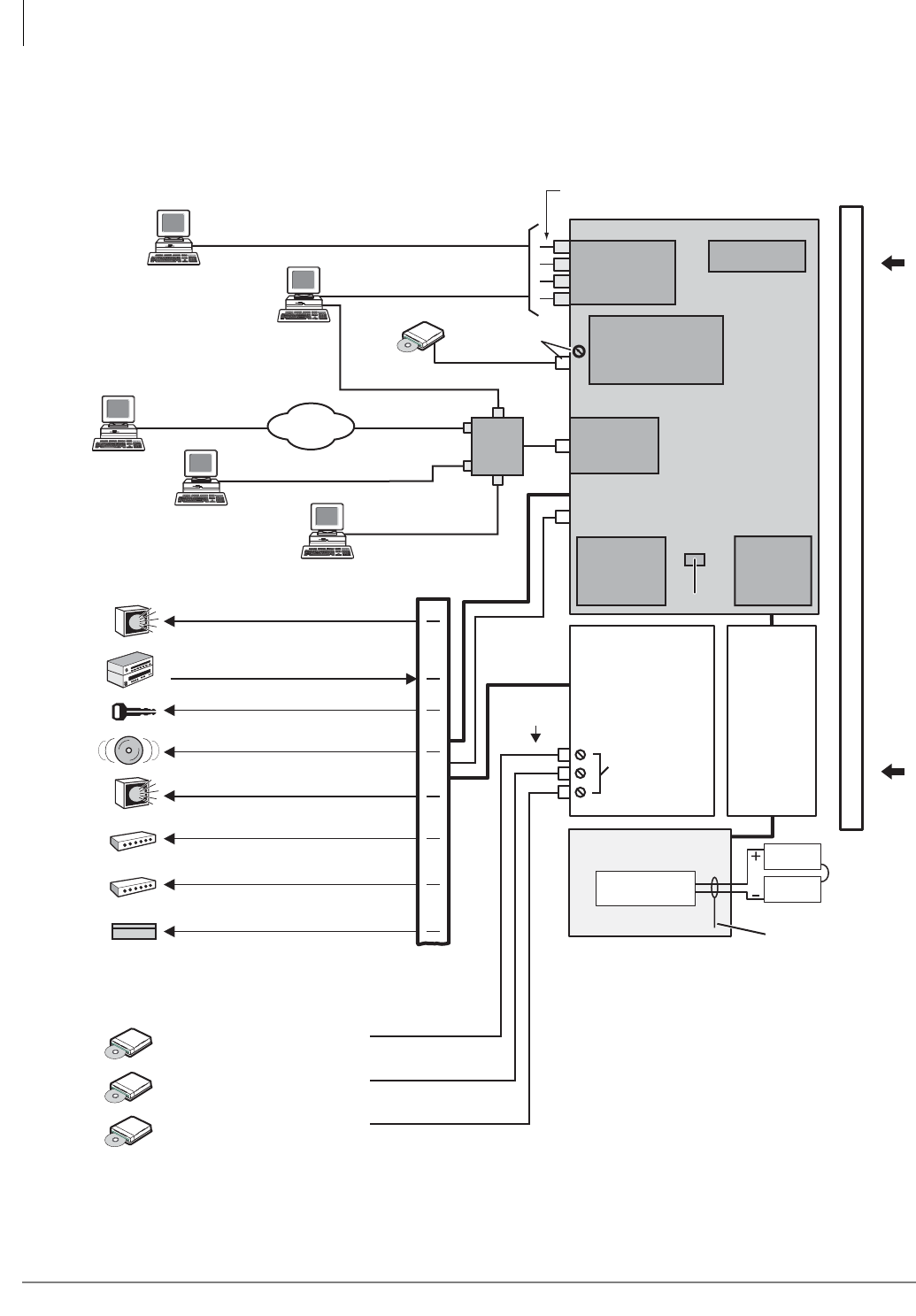
The Functional Block Diagrams show the PCBs and interface connectors used for connecting the
station.
Figure 2-5 CTX100 System Processor and Option Interface PCBs
Data and Speech Highway
6752
ACTU
Processor PCB
(one or two per system)
Relay Contacts
Virtual slot 09
ASTU
Relay Contact (Programmable)
RCA Jack (600 ohm Page Output)
MOH/BGM
RCA Jacks
Battery Charger
ABCS
12V
Battery
12V
Battery
(2 or 4 Batteries)
ABTC - 3m Cable
MOH/BGM Jack
+Volume Control
APSU112
Cabinet
Power Supply
MOH/BGM
Volume Controls
Up to Four Programmable Serial (RS-232)
Port Modular Jacks Available
ACD
(CSTA)
SMDR
Call Accounting
Remote CTX
WinAdmin PC
Local CTX
WinAdmin
Notes
1. Optional.
2. License Control.
Music Source 1: Background Music
and/or Music-on-hold
Music Source 2: Background Music
and/or Music-on-hold
Music Source 3: Background Music
and/or Music-on-hold
BSIS
2
(Optional)
Conference
SW with PAD
Interface PCB
BIOU
1
1
1
AMDS
Remote Maintenance
Modem
1
1
Ethernet
Interface
DTMF/ABR
Receivers
RJ45
Smart Media
Maintenance
and
Customer
Database
License
Internet
Music Source: External Zone Page
Background Music
Door Lock Control Relay
External Zone Page Relays (4 Zones)
External Page Amplifier (600 ohm Output)
Main Distribution
Frame (MDF)
Night Bell Control Relay
Amplified Page Output (3 Watts)
BGM Mute Control Relay
Night Control Relay
25 Pair
Hub
or
LAN
SMDI or Toshiba Proprietary
Integration
Toshiba Proprietary Soft Key LCD Link
Stratagy ES
Voice Mail
On this page, all equipment, except Stratagy ES,
connected to the system processor PCBs and
BIOU PCB is customer-supplied.