


Strata CTX670 Installation
Cabinet Installation Considerations
4-6 Strata CTX I&M 06/04
Cabinet Installation Considerations
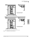
The Base (CHSUB672) and Expansion (CHSUE672) Cabinets can be wall or floor mounted. To
make it easier to add cabinets (after the initial installation) when a customer needs to expand,
install the Base Cabinet on top for wall-mount installations and on the bottom for floor-mount
installations.
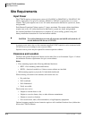
The dimensions of the Base and Expansion Cabinets are:
Height: Base Cabinet: 11 3/4 inches
Height: Expansion Cabinet/Remote Expansion Cabinet: 10 inches
Width: 26 1/2 inches
Depth: 10 5/8 inches
Weight: approx. 30.5 lbs. (14 kg.)
Note The weight approximates a cabinet completely filled with PCBs. Weight may vary slightly,
depending on PCBs.
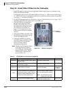
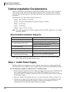
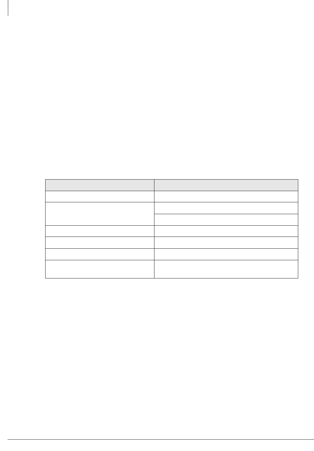
Recommended Installation Sequence
Note Each cabinet requires four wood screws (#12 X 2 inch size) for wall mount installation.
Wood screws are not provided with the system.
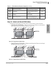
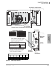
Step 1: Install Power Supply
The Base and Expansion Cabinets are factory-shipped without the power supply installed. The
CTX670 cabinets use the BPSU672 power supply, which is different from the DK280 or DK424.
³ To install power supplies in cabinets of new or installed systems
1. Remove the power supply from its box. The power supply AC power cord for 120VAC and the
power supply mounting screws are provided with the KSU cabinet. If the system is to be
powered by 208VAC or 240VAC, another powered cord, BACL240 must be ordered separately
for each power supply.
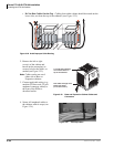
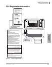
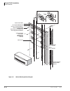
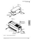
2. Make sure that the front and right side covers are removed from the cabinet (see Figure 4-5).
3. Slide the power supply into the right side of the cabinet so that its four mounting holes align
with the four cabinet mounting holes. (Make sure that the two backplane FG wires are
positioned between the FG wire holder and the power supply.)
Step Reference Information
1. Install power supplies in cabinets. “Install Power Supply” on page 4-6.
2. Mount cabinets on wall or floor.
“Wall Mounting the Base (Top) Cabinet” on page 4-10.
“Cabinet Floor Mounting” on page 4-33.
3. Install ground wiring. “Ground the System” on page 4-18.
4. Install AC power cabling to cabinets. “Install AC Power Components” on page 4-20.
5. Install reserve power cabling. “Install Reserve Power” on page 4-29.
6. Install PCBs and PCB cabling.
Figures 4-38~4-23, 4-42 and the section titled “Install
Processor and Universal PCBs” on page 4-43.