


CTX28 Installation
Installing the CTX28 Cabinet
1-18 Strata CTX I&M 06/04
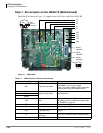
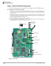
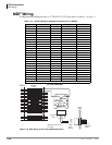
Step 7: Install the BSIS1A (optional)
The BSIS provides RS-232 serial ports.
³ To install the BSIS1A, align the BSIS1A pins over the GCTU1A and press down firmly (see
Figure 1-6).
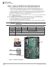
Step 8: Install the HPFB-6 (Reserve Power Battery/Charger)
One or two HPFB-6 optional units can be added to the CTX28 to provide reserve power. The
amount of reserve power time depends on the hardware (see Table 1-12). The table below is an
estimate of battery backup time based on the premise that the HPFB-6 unit(s) are fully charged at
the time of AC power failure. This estimated backup time is based on low call traffic, the time
estimates will be reduced by as much as half with extreme heavy traffic volumes.
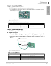
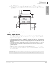
1. Place the HPFB-6 directly below the Strata CTX28 KSU. See Figure 1-14 for minimum
clearance requirements. A second HPFB-6 can be installed directly below the unit to supply
backup reserve power.
2. Mark the location of the two screw holes, then drill holes.
3. Screw the two screws two-thirds into the mounting surface.
4. Hang the HPFB-6 on the screws then tighten the screws into the mounting surface.
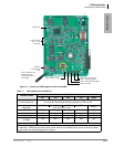
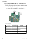
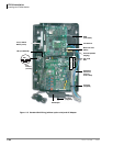
5. Plug the first HPFB-6 connector into BATT connector P10 on GMAU.
6. Connect a #10 ground AWG wire from the HPFB-6 “FG” screw to the CTX28 screw labeled
“TB1” (Figure 1-2).
Note The CTX28 should be plugged into AC power and the DC power switch should be turned
On when installing the HPFU-6. The HPFU-6 will not start to operate if AC power is not
available during the initial installation.
7. The 24VDC LED on the HPFB-6 should light. If it does not light, press the battery Off switch
with a pencil point or other small-tipped object.
8. Dress and tie-wrap the HPFB-6 cables.
9. To mount a second HPFB-6, repeat Steps 1~4, then plug the second HPFB-6 connector in the
first HPFB-6 and connect an FG wire between each HPFB-6 FG screw.
10. To test the HPFB-6, remove the CTX28 AC plug from the AC outlet. The CTX28 AC LED will
go out, but the CTX28 DC LED remains on. Also the system remains in normal working order
and the HPFB-6 24V LED remains on.
11.If it is desired to turn off the HPFB-6 (after loss of AC power), use a pencil or other sharp
object to press the Battery Off switch.
CAUTION! Once the HPFB-6 is turned Off or unplugged (during AC power loss) it will not
operate again until AC power is restored to the CTX28 KSU.
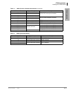
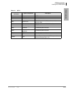
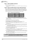
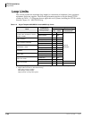
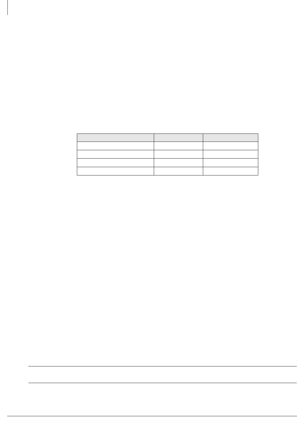
Table 1-12 CTX28 Reserve Power Duration Estimates
Hardware 1 HPFB-6 2 HPFB-6
3CO/8DKT - No GVMU 1 hr. 40 min. 3 hr. 20 min.
3CO/8DKT - with GVMU 1 hr. 30 min 3 hr.
6CO/16DKT - No GVMU 1 hr. 5 min. 2 hr. 10 min.
6CO/16DKT - with GVMU 1 hr. 2 hr.