


Peripheral Installation
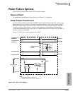
Power Failure Options
12-26 Strata CTX I&M 06/04
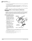
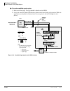
Power Failure Emergency Transfer (DPFT) Installation
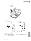
1. Mount the DPFT on or near the MDF.
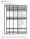
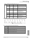
Note See Chapter 10 – MDF PCB Wiring, DPFT/MDF interconnecting tables.
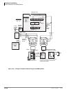
2. Using 25-pair cables with amphenol-type connectors (female for DPFT connector J1, male for
DPFT connector J2), connect the DPFT to two 66-type quick-connect blocks.
3. Connect the CO lines selected for emergency use to the DPFT J1-block “CO-TIP” and “CO-
RING” terminals.
4. Connect the RCOU, RCOS (or PCOU) circuits related to the emergency CO lines to the DPFT
J1-block “RCOU-TIP” and “RCOU-RING” terminals.
5. Connect the standard telephone stations selected for emergency use to the DPFT J2-block
“TEL-TIP” and “TEL-RING” terminals.
6. Connect the RSTU, RDSU/RSTS or PSTU standard telephone circuits related to the emergency
standard telephones to DPFT J2-block “PSTU/ RSTU-TIP” and “PSTU/RSTU-RING”
terminals.
7. Connect the DPFT to the RDSU/RSTU/PSTU DG and -24V terminals (See Chapter 10 – MDF
PCB Wiring for RSTU/PSTU and RCOU/PCOU wiring/interconnecting details). The -24V
(Pin 25) and DG (Pin 50) ground terminals are available on the RSTU2, RDSU, or PSTU only.
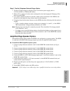
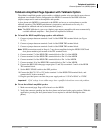
³ To test the operation of the DPFT
1. Turn the system power switch Off.
2. Verify that CO dial tone is available at each standard telephone connected to the DPFT.
3. Call back to each telephone using an outside line.