


T1
RDTU Installation
8-8 Strata CTX I&M 06/04
RDTU3 Self Test and CSU Test Switch
1. Remove the RJ45 cable to perform the Self Test.
2. Set the SW8 and SW9 switches to On (see Table 8-5).
3. After self check passes, put the switches back into position for normal operation and insert the
RDTU PCB back into the appropriate slot.
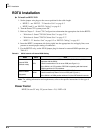
RDTU3 Equalizer Switches
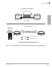
The distance between the Strata CTX, RDTU and CSU or RDTU to other Customer Premise
Equipment (CPE) T1 may vary (0~655 ft.) as shown. (See “RDTU3 Cabling” on page 8-5.) The
RDTU interface transmitter must be equalized and its impedance must be matched to the cable
length connecting the RDTU to the CSU or other CPE, T1.
³ Set the appropriate SW1 Equalizer Switch setting and set SW1 to the setting that matches the
RDTU cable length (see Table 8-6).
RDTU3 Loop Back Jumper Plugs
The RDTU PCB provides jumper plugs for loop back testing. Loop back tests are described in
“Loop Back Testing” on page 8-19. See Table 8-5 for switch settings for Loop Back tests.
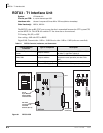
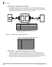
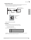
RDTU3 Front Panel Indicators
The RDTU3 PCB provides seven LED indicators to show the status of RDTU: Busy or Idle
condition, Alarm status, and Synchronization status. See Table 8-2 for the function of each status
LED. Figure 8-1 shows the LED locations. Busy LED (BSY)—Turns on when one or more RDTU
channels (lines) are in use. Also, when the RDTU does not receive the far end 1.544 mbs carrier
signal, the RDTU will cause the BSY to be on steady.
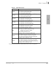
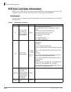
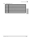
Table 8-5 SW8, SW9 RDTU3A Self and CSU Test
Mode SW8 and SW9
RDTU3A self test and CSU test mode
Both On
All LEDS turn Off
except PSYNCH
or SYNCH
Normal operation (non-loop back) Both Off
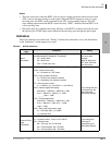
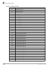
Table 8-6 Equalizer Setting Switch
Mode Feet from CTX SW4 SW5 SW6
Short 0 to 133 feet Off Off Off
Semi-short 133 to 266 feet On Off Off
Medium 266 to 399 feet Off On Off
Semi-long 399 to 533 feet On On Off
Long 533 to 655 feet X X On
X = Doesn’t matter.