


PCB Installation
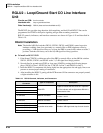
RMCU/RCMS – E911 CAMA Trunk Direct Interface
Strata CTX I&M 06/04 6-39
PCB Installation
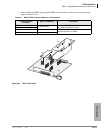
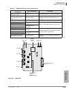
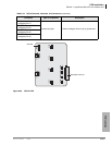
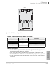
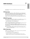
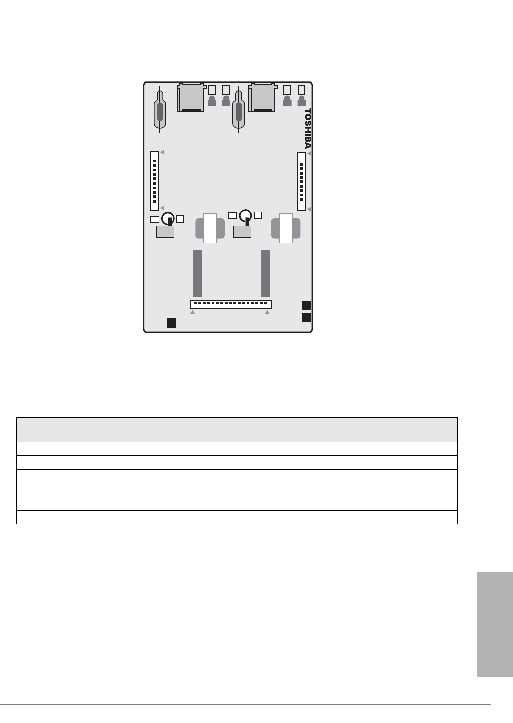
Figure 6-28 RCMS Subassembly (stand-alone)
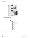
RMCU Installation
1. Insert the RMCU (component side facing right) into the appropriate slot, and apply firm, even
pressure to ensure proper seating of the connectors.
2. Gently pull the unit outward. If the connectors are properly seated, a light resistance is felt.
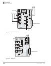
3. Wire the RCMS jacks, J4 and J5, to the network CAMA trunks per Figure 10-9 on page 10-17.
4. Test the CAMA trunk and set the 3-dB Pad switches, SW101 and SW 201, for the appropriate
volume level.
Table 6-19 RCMS Subassembly Controls, Indicators, and Connectors
Controls, Indicators, &
Connectors
Type of
Component
Description
SW101 Switch 3-dB Pad switch for circuit 1 or 3.
SW201 Switch 3-dB Pad switch for circuit 2 or 4.
J1
Connector Blocks
Jacks to connect to RMCU.
J2 Jacks to connect to RMCU.
J3 Jacks to connect to RMCU.
RJ11 6-pin modular connector Network interface jack to CAMA trunk.
RCMS1A
600 / 600
600 / 600
RCMS1A -CM V.1
RCMS1
CB
NB
CB
NB
5817
J2
J3
SW101
SW201
J1
J4
J5
PAD
3
0
PAD
3
0