


T1
T1
RDTU Installation
Strata CTX I&M 06/04 8-5
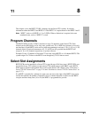
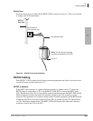
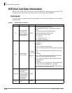
Ferrite Core
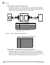
Install the Ferrite core provided with the RDTU3 PCB, as shown in Figure 8-2. This core is needed
to comply with FCC requirements.
Figure 8-2 RDTU3 Ferrite Core Installation
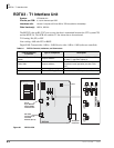
RDTU3 Cabling
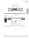
Each RDTU3 T1 PCB requires the following connecting equipment and cables to provide service
(see the following sections and Figure 8-3).
RDTU3 to Network
If the RDTU3 must interface to a public telephone network or common carrier T1 circuit, the
RDTU3 must be connected to a CSU. Use the RDTU3-CBL-KIT to connect the RDTU to the
CSU. The function of the CSU is to provide the required interface between the RDTU PCB and the
Public Telephone or Carrier Network. The interface created by the CSU normally provides
protection and capabilities for loop back testing both the Network equipment and the RDTU PCB.
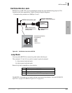
Connecting the CSU to the Network Interface Unit (NIU) is specified by the CSU manufacturer—
see CSU installation documentation. The RDTU3-CBL-KIT supplies the cables and connectors
required to connect the CSU to the NIU.
One Turn
CAT5 Shielded Cable
RDTU3
Side View
6306
Note: The Ferrite core must be
as close as possible to the PCB.
RJ-45 Network/
CSU Interface Jack