


ISDN Interfaces
RPTU Interface Unit
7-8 Strata CTX I&M 06/04
RPTU Interface Unit
Circuits per PCB:
24 channels
Interfaces with:
ISDN PRI
Older Version(s):
none
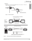
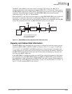
The RPTU provides 24 channels for ISDN PRI service. Network connection using RPTU PRI
interface requires installation of a customer-provided CSU in most locations of the U.S. Refer to
“CSU Requirements” on page 7-3 for CSU installation.
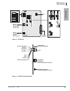
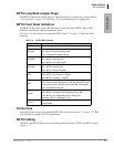
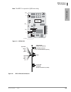
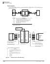
Switches, jumpers, and interface connectors are described in Table 7-5. The RPTU’s LEDs show
operation status (see Figures 7-4 and 7-5 on page 7-9 and Table 7-6).
Testing procedures (local and remote loop back) are in “Loop-back Test” on page 7-34.
RPTU Installation
Before installing a RPTU PCB into a Strata CTX system, refer to Chapter 2 – Strata CTX
Configuration:
• “Worksheet 6: Strata CTX670 Cabinet Slots” on page 2-37
• “ISDN PRI Digital Line PCBs” on page 2-40 (mentioned above in slot assignments)
³ To install an RPTU PCB
1. Set the jumper wire plugs JP1 and JP2 (LB) to the Off position.
2. Turn the Strata CTX system power Off.
3. Insert the RPTU (component side facing right) into the appropriate slot and apply firm, even
pressure to ensure proper seating of connectors.
4. After installing the RPTU, gently pull the PCB outward. If the connectors are properly seated, a
slight resistance is felt.
Note For cabling information and requirements, refer to “BPTU and RPTU Cabling” on page
7-11.
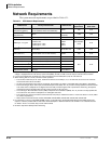
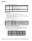
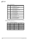
Table 7-5 RPTU Switches, Jumpers, and Connectors
Switches/Jumpers/Connector Description
SW1 (Line length adjustment switch)
Matches the RPTU impedance to the impedance of the
line (length between the CSU and the RPTU). Refer to
Table 7-7 on page 7-10.
SW2 (Reset switch)
1
1. If this switch on the Primary Clock source RPTU is pressed, the clock source will automatically revert to the
Secondary Clock source.
Resets or initializes the RPTU firmware. Press this switch
to correct an out-of-service condition, or just prior to
connecting to the Network PRI.
JP1 & JP2 (Loop-back jumpers)
Makes loop-back tests of the cabling between the ISDN
Network switch, CSU, and RPTU.
J1 8-pin Modular Connector (RJ45) Connects the RPTU to the CSU/network PRI ISDN line.
J2 6-pin Modular Connector (RJ11)
Connects the RPTU to a terminal or PC to monitor
D-channel data.