


CTX28 Installation
Installing the CTX28 Cabinet
Strata CTX I&M 06/04 1-19
CTX28 Installation
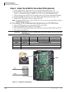
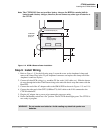
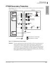
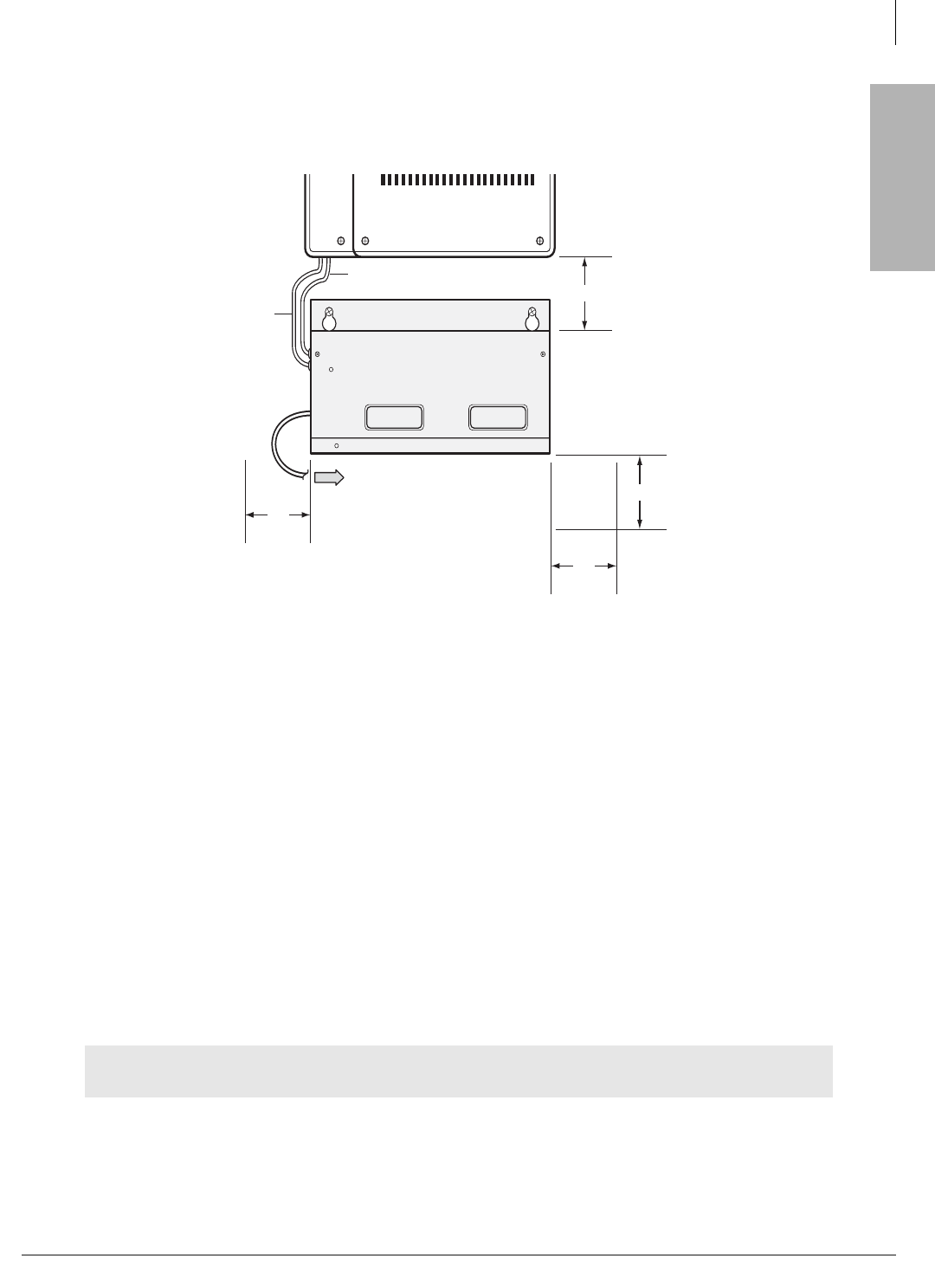
Note The CTX28 KSU does not provide a battery charger, the HPFB-6 contains built-in
batteries and a battery charger; therefore, do not connect any other type of batteries to
the CTX28.
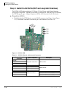
Figure 1-14 HPFB-6 Reserve Power Installation
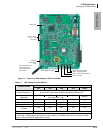
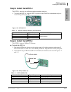
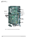
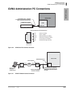
Step 9: Install Wiring
1. Refer to Figure 1-15 for the following steps. Loosen the screw on the Amphenol clamp and
remove the clamp. Plug in the 25-pair Amphenol connector and replace the clamp to hold the
Amphenol connector in place.
2. Connect all other PCB wiring (e.g., modular CO line cords, LAN cable, etc.). Slide the shorter
tie-wrap through the holder. Then fasten wiring to the unit with the tie wrap that comes with the
Base KSU.
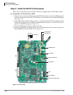
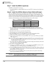
3. Connect the end of the AC adapter cable to the GMAS PCB as shown in Figures 1-15 and 1-16.
4. Connect the other end of the GETS (100Base TX) LAN cable to the LAN connected to the
CTX WinAdmin PC.
5. Plug the AC adapter into a power strip connected to an power outlet.
6. Put the On/Standby switch into “On” position. The DC LED should light green. The CTX28 is
now ready to program.
WARNING! Do not smoke near batteries. Avoid creating any electrical sparks near
batteries.
2“
From Second HPFB (optional)
To P10 Connector (see Fig. 1-2)
HPFB Unit:
Reserve Power Battery
and Charger (optional)
#10 AWG HPFB
FG Wire to TB1
(see Fig. 1-2)
7253
2“
2“
2“