Strata CTX670 Installation
Install Processor and Universal PCBs
Strata CTX I&M 06/04 4-43
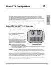
Strata CTX670
Installation
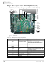
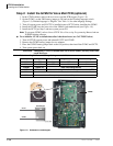
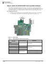
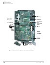
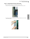
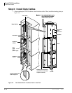
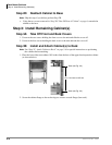
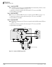
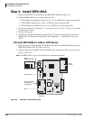
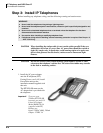
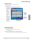
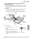
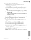
Step 7: Install Processor and Universal PCBs
This section provides procedures for the installation of CTX670 processor (or common control)
PCBs.
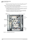
The CTX670 system Base and Expansion Cabinets are shipped empty. PCBs are not installed at
the factory. Universal PCBs must be placed according to the configuration information obtained
and developed in Chapter 1 – Configuration. PCB installation is in Chapter 6 – PCB Installation.
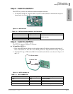
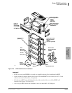
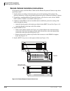
• Install PCBs only after installing the Base Cabinet and, if applicable, Expansion Cabinets per
the Cabinet Installation section in this chapter.
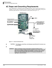
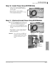
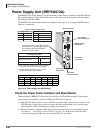
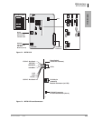
• Be sure the power supply has been tested and the ground has been checked (see “Install Power
Supply” on page 4-6.
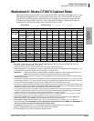
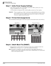
• Install universal slot PCBs per the CTX670 configuration guidelines (see “Worksheet 6: Strata
CTX670 Cabinet Slots” on page 2-37.
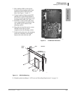
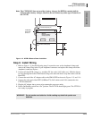
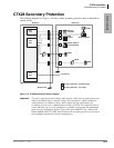
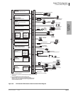
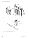
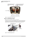
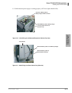
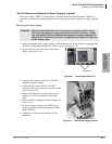
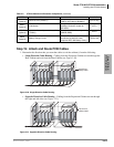
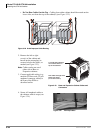
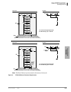
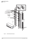
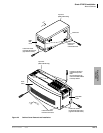
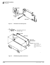
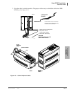
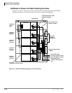
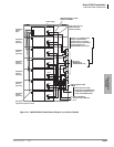
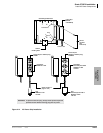
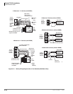
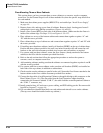
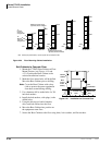
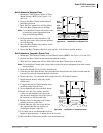
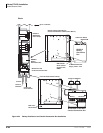
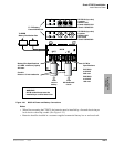
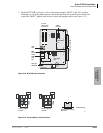
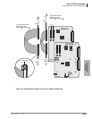
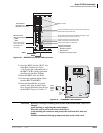
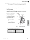
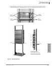
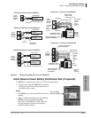
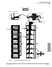
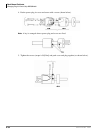
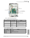
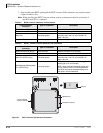
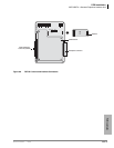
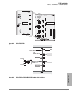
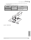
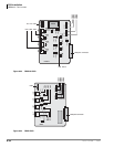
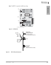
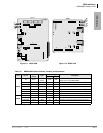
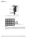
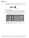
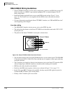
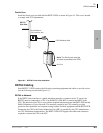
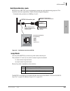
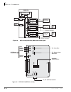
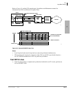
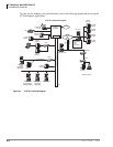
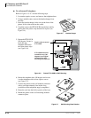
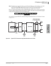
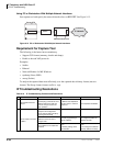
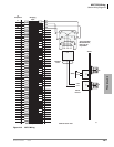
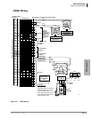
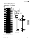
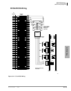
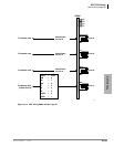
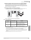
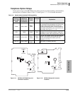
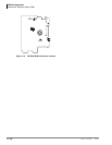
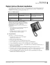
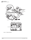
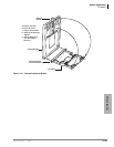
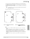
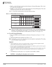
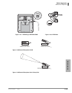
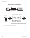
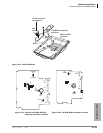
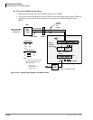
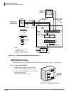
• Install the metal mesh shield, B50MT around the 25-pair cables connected to PCBs per Figure
4-10.
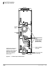
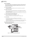
Important! After all PCBs are installed, be sure to slide the locking bar into the lock position to
ensure that the PCBs remain in place (see Figure 4-3 on page 4-9).
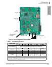
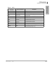
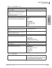
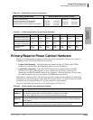
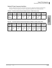
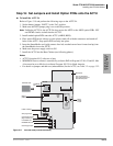
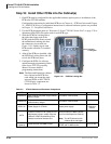
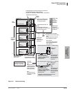
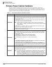
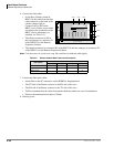
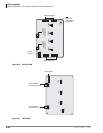
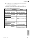
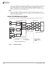
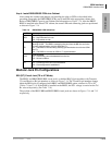
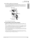
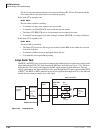
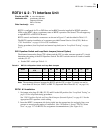
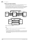
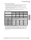
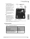
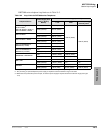
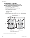
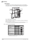
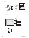
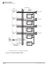
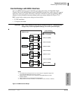
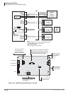
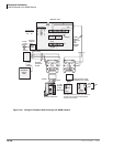
PCB Installation Considerations
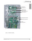
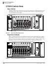
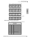
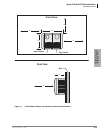
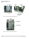
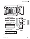
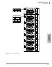
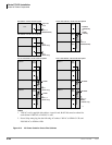
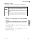
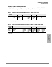
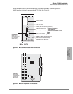
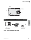
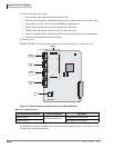
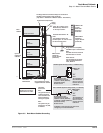
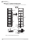
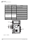
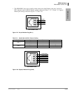
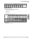
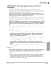
The Base Cabinet has ten slots. The first two slots, labeled “B101” and “B102” are reserved for the
common control unit and future feature upgrades. The next eight slots (labeled “S101” ~“S108”)
are universal and capable of hosting any of the station, line, and option interface PCBs compatible
with the CTX670 systems.
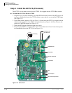
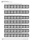
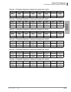
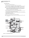
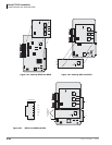
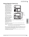
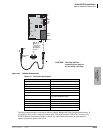
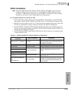
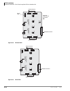
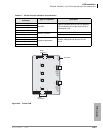
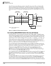
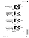
The Expansion Cabinets have ten universal slots, labeled “S_01,” “S_02,” etc., where the blank
space of the label represents the number of the Expansion Cabinet. Like the universal slots in the
Base Cabinet, these universal slots are capable of hosting any of the station, line, and option
interface PCBs.
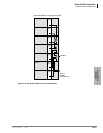
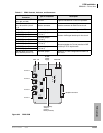
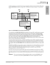
Cabinets are numbered from 1 to 7. The Base Cabinet is numbered 1; the first Expansion Cabinet,
number 2; the second Expansion Cabinet, number 3, etc. See the CTX670 Configuration and PCB
Installation section for details.
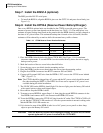
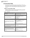
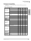
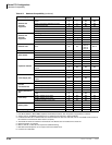
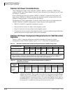
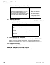
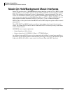
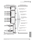
PCB Option Considerations
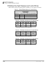
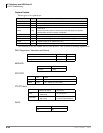
CTX670 PCBs can be configured for a variety of hardware and software options. Hardware
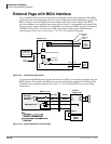
options are defined as either internal (generally related to optional PCB subassemblies) or external
(related to connection of peripheral equipment such as background music, voice mail, etc.).
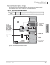
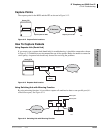
Hardware Options
Some PCBs must be configured for hardware options prior to installation of the PCB in the
cabinet. Configuration instructions for internal hardware options are provided in the individual
PCB installation procedures in this chapter and in Chapter 6 – PCB Installation. Configuration
instructions for external hardware options are provided in Chapter 12 – Peripheral Installation.
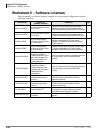
Software Options
PCBs are configured for software options through programming, following the installation
instructions of the PCBs. A programming overview for each PCB is provided in the individual