


ISDN Interfaces
BPTU Interface Unit
7-4 Strata CTX I&M 06/04
BPTU Interface Unit
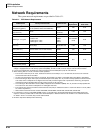
System:
DK424, DK40i, CTX100 & 670
Circuits per PCB:
24 channels per PCB
Interfaces with:
ISDN PRI
Older Version(s):
none
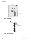
The BPTU has an RS-232C port to trace data that is transmitted between the CTX system CPU and
the BPTU.
T1 Framing: ESF
Line cording: B8ZS
Digital PAD: Transmit side +6dB to -15dB. Receive side +6dB to -15dB (software controlled)
BPTU Installation
Power Factor
BPTUA uses 5V only. 5V power factor = 2.30
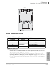
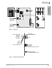
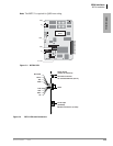
³ To install an BPTU PCB
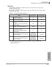
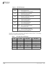
1. Look for IC19 on the BPTU PCB. If it is on the PCB, move the SW10 jumper to “ROM.” If
IC19 is not on this PCB, leave the jumper on the “CPU” setting (see Table 7-1).
2. If you want to run the PCB Self Test, refer to BPTU Self Test.
3. Turn the Strata CTX system power Off.
4. Insert the BPTU (component side facing right) into the appropriate slot and apply firm, even
pressure to ensure proper seating of connectors.
Refer to Chapter 2 – Strata CTX Configuration:
• “Worksheet 5: Strata CTX100 Cabinet Slots” on page 2-26
...or “Worksheet 6: Strata CTX670 Cabinet Slots” on page 2-37
• “ISDN PRI Digital Line PCBs” on page 2-40 (mentioned above in slot assignments)
5. After installing the BPTU, gently pull the PCB outward. If the connectors are properly seated, a
slight resistance is felt.
6. For cabling information and requirements, refer to “BPTU and RPTU Cabling” on page 7-11.