


Strata CTX100-S/CTX100 Installation
Installing the CTX100 Cabinet
Strata CTX I&M 06/04 3-9
Strata CTX100-S/
CTX100 Installation
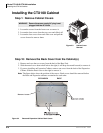
Step 13: Mount the Expansion Cabinet (if required)
1. Turn Base Cabinet DC power switch Off. Remove the four screws on the right side cover of the
Base Cabinet.
2. Remove four screws from the right side of the Base Cabinet (since they will interfere with
attaching the Expansion Cabinet to the Base Cabinet later).
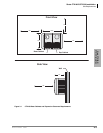
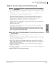
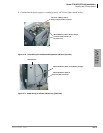
3. Remove the Expansion Cabinet back cover from the Expansion Cabinet (see Figure 3-4).
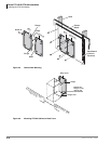
4. Place the Expansion Cabinet back cover next to the Base Cabinet back cover, making sure
expansion back cover hooks fit into the base back cover flanges (see Figure 3-5).
5. Mark the location of the four screw holes – there is one on each corner.
Make sure the location of the Expansion Cabinet meets the minimum clearance requirements
specified in Figure 3-1 on page 3-3.
6. Drill holes on these marks.
7. Place the Expansion Cabinet back cover on the wall back board and secure the back cover to
the back board with four screws.
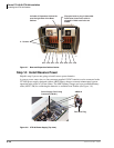
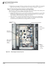
8. On the right side of the AMAU motherboard inside the Base Cabinet, flip open the top and
bottom locks for data ribbon cable plug. Plug in the data ribbon and close the locks. Feed the
ribbon through the side hole of the Base Cabinet.
9. To mount the Expansion Cabinet, position it onto the back cover hangers.
Note Position the cabinet over the bottom right hanger first, and then carefully tilt the cover over
the top two hangers.
10.Slide the Expansion Cabinet to the left, feeding the data ribbon cable through the side hole of
the Expansion Cabinet.
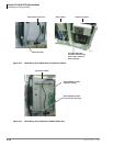
11. Finish by securing the Expansion Cabinet to the Base cabinet with the two screws in front of
the cabinets where they join together. The expansion cabinet left-side flange fits over the Base
cabinet right side flange (see Figure 3-7).
12. On the AMAU motherboard of the Expansion Cabinet, flip open the two data ribbon locks,
plug in the data ribbon and close the locks. The data ribbon cable should now be connected to
the Base and Expansion cabinets.
13. Install PCBs into the Expansion Cabinet; follow the instructions in “Step 18: Install Other
PCBs into the Cabinet(s)”.
Note The Base Cabinet DC power switch will be the master control for turning the DC power of
both cabinets On/Off.
14. Attach the outside covers on the Expansion Cabinet.
WARNING! To prevent electrical shock, make sure the power supply is not plugged into
the AC outlet.