


ISDN Interfaces
RBSU/RBSS Interface Units
Strata CTX I&M 06/04 7-17
ISDN Interfaces
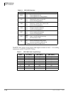
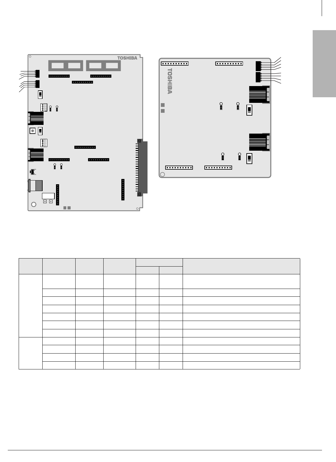
Table 7-8 RBSU/RBSS Option Switches, Jumpers, and Connectors
PCB Circuit
Option
Switch
Type
Circuit Type
Description
TE NT
RBSU
All SW 1
Push-
button
N/A N/A
Resets firmware on all circuits of RBSU/RBSS.
Drops calls off the RBSU/RBSS.
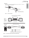
1 SW 2 Jumper X X Causes the circuit to operate as TE or NT
1
.
1. Requires programming to set as TE or NT.
1 SW 3 Slide On Off Switches a 100-ohm resistor in/out of the circuit.
1 SW 4, 5 Jumper N/A On Switches PS-1 in/out of the circuit.
2 SW 6 Jumper X X Causes the circuit to operate as TE or NT
1
.
2 SW 7 Slide On Off Switches a 100-ohm resistor in/out of the circuit.
2 SW 8, 9 Jumper N/A On Switches PS-1 in/out of the circuit.
RBSS
3 (NT only) SW 1 Slide On Off Switches a 100-ohm resistor in/out of the circuit.
3 (NT only) SW 3, 4 Jumper N/A On Switches PS-1 in/out of the circuit.
4 (NT only) SW 2 Slide On Off Switches a 100-ohm resistor in/out of the circuit.
4 (NT only) SW 5, 6 Jumper N/A On Switches PS-1 in/out of the circuit.
RBSU1A-CM V.1
RBSU1
2789
RBSU1A
BSY
TS
LOS
FS
BSY
TS
LOS
FS
P2 P4
P7
SW7
SW6
SW9
SW8
J2
SW3
SW2
J1
P5
P6
P3
SW5
SW4
SW1
J3
P8
P9
TB3
PFT
contacts
TB1 TB2
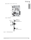
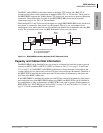
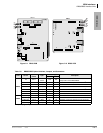
Figure 7-11 RBSU PCB
SW2
SW3
SW4
SW5
SW6
RBSS1A-CM V.1
SW1
F
J4 J2
J3 J5
2788
RBSS
BSY
TS
LOS
FS
BSY
TS
LOS
FS
J7J6
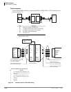
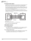
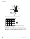
Figure 7-12 RBSS PCB