


Strata CTX100-S/CTX100 Installation
Installing the CTX100 Cabinet
3-12 Strata CTX I&M 06/04
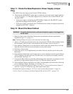
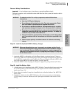
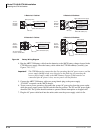
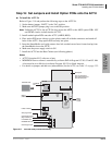
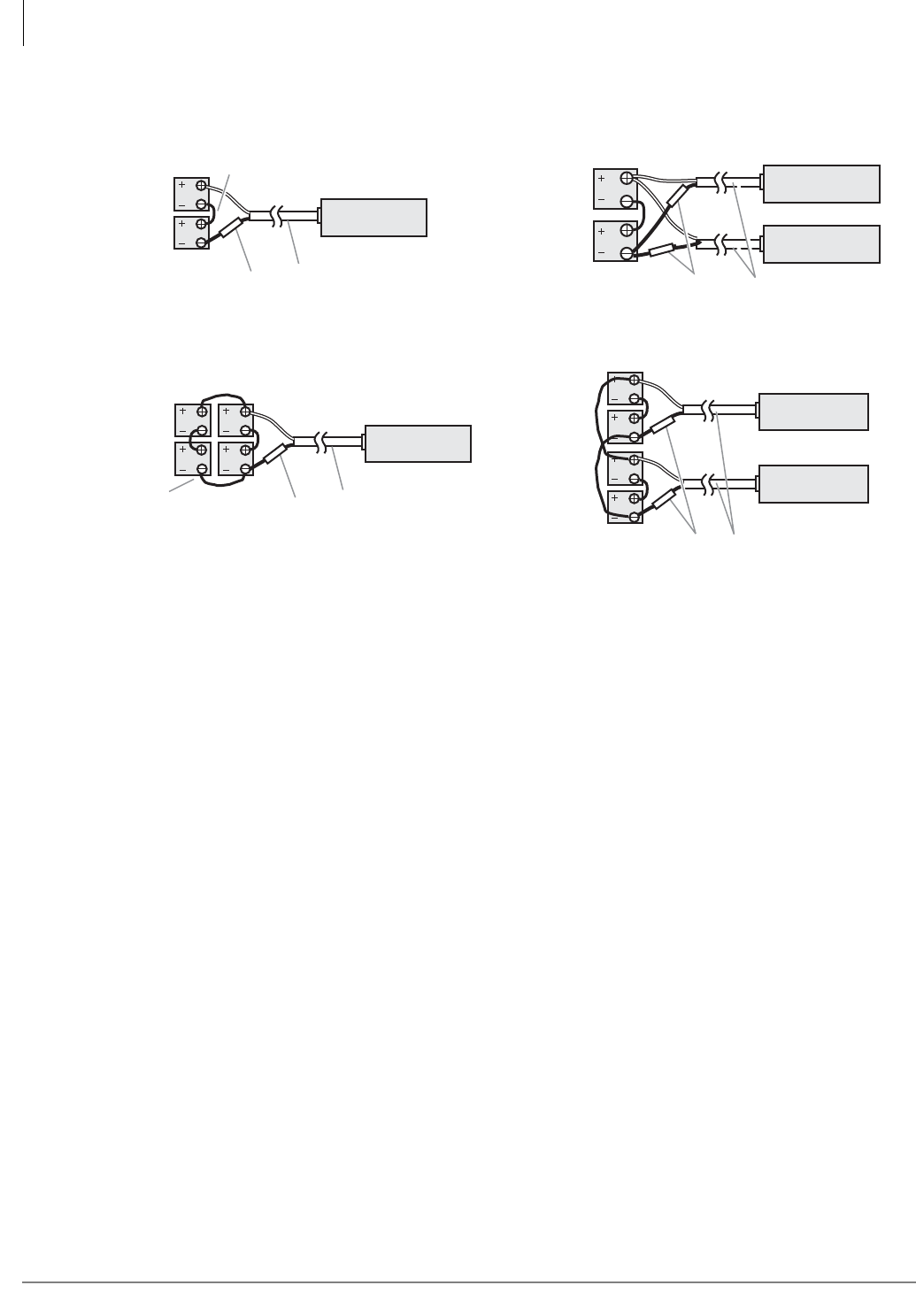
Figure 3-9 Battery Wiring Diagram
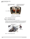
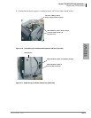
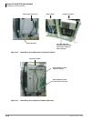
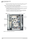
4. Run the ABTC-3M battery cable from the batteries to the ABCS battery charger located in the
CTX100 power supply. Dress the battery cable within the CTX100 cabinet(s) carefully (see
Figures 3-10~3-13).
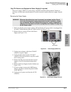
Important! The CTX100 must be connected to the live operating (hot) AC power source, and the
power supply On/Off switch set to On prior to the final step of connecting the
reserve power battery cable to the ABCS battery charger. If the batteries are
connected after AC power is lost, reserve power will not function.
5. Connect the ABTC-3M battery cable two-prong female plug to the power supply
“CN-BAT” receptacle on the ABCS charger.
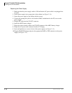
6. To test reserve power operation, disconnect the system AC power plug from the source outlet
while the power supply power On/Off switch in the On position. The AC and DC power lights
should be Off. The system should continue to operate without interruption or dropped calls.
7. Plug the AC power cable back into the outlet; make sure the power supply switch is On.
2-Batteries/1-Cabinet
12 Volt
Batteries
80 AMP/
HR Each
ABTC-3M Cables (9 ft.)
–
+
ABCS CN-BAT
Connnector
10A Fuse
Black jumper wire
All Jumper Wires
must be 16 AWG Wire
ABCS CN-BAT
Connnector
ABCS CN-BAT
Connnector
4-Batteries/2-Cabinets
ABTC-3M Cables (9 ft.)
10A Fuse
Expansion Cabinet
Base Cabinet
12 Volt
Batteries
80 AMP/
HR Each
–
+
–
+
ABCS CN-BAT
Connnector
ABCS CN-BAT
Connnector
2-Batteries/2-Cabinets
10A Fuse
Exp. Cabinet Power Supply
Base Cabinet Power Supply
ABTC-3M Cables (9 ft.)
12 Volt
Batteries
80 AMP/
HR each
–
+
–
+
5934
4-Batteries/1-Cabinet
12 Volt
Batteries
80 AMP/
HR Each
ABTC-3M Cables (9 ft.)
–
+
ABCS CN-BAT
Connnector
10A Fuse
Base Cabinet Power Supply
Base Cabinet Power Supply