


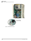
PCB Installation
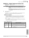
BSTU/RSTU – Standard Telephone Interface Unit
6-12 Strata CTX I&M 06/04
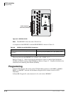
3. After installing the BSTU, gently pull the BSTU outward. If the connectors are properly mated,
a light resistance is felt.
Note When installing the RSTU3 into an existing system, system power must be cycled only if
the MW mode (P11) is changed.
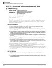
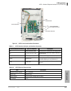
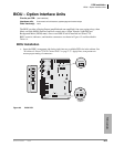
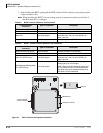
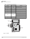
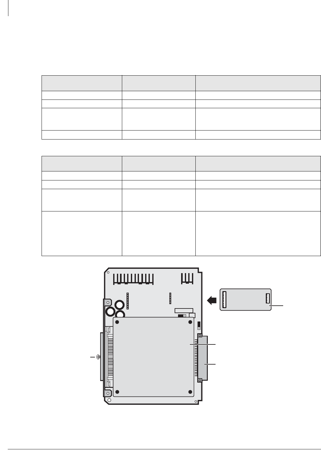
Figure 6-7 BSTU Controls and Interface Connectors
Table 6-5 BSTU Controls, Indicators, and Connectors
Control/Indicator/
Connector
Type of Component Description
R48S connector P6 9-pin connector Interface connector to P6 of R48S.
R48S connector P7 6-pin connector Interface connector to P7 of R48S.
Mu/A P10 3-terminal jumper
Mu Law or A Law PCM companding. (Must be
set to Mu Law in the U.S. and Canada). No
strap = Mu Law.
Ring-time P12 3-terminal jumper Always set jumper to “REN3.”
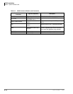
Table 6-6 RSTU1, 2 and 3 Controls, Indicators, and Connectors
Control/Indicator/
Connector
Type of Component Description
R48S connector P6 (RSTU) 9-pin connector Interface connector to P6 of R48S.
R48S connector P7 (RSTU) 6-pin connector Interface connector to P7 of R48S.
Mu/A P10 (RSTU3 only) 3-terminal jumper
Mu Law or A Law PCM companding. (Must be
set to Mu Law in the U.S. and Canada). No
strap = Mu Law.
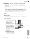
MW (Message Waiting) Mode
P11 (RSTU3 only)
3-terminal jumper
CON = Electronically controlled message
waiting light (U.S. and Canada).
NOR = Relay controlled message waiting light.
Do not use this in the U.S. and Canada since
this option may cause message waiting cross-
talk noise in some installations.
BSTU1A
RING-TIME
P12
P7
P6
50-Pin Amphenol
Connector (Female)
6592
Backplane Connector
Mu A
P10
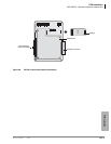
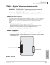
P6
P7
R48S
Optional
SBSS Subunit