


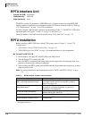

ISDN Interfaces
BPTU Installation
Strata CTX I&M 06/04 7-7
ISDN Interfaces
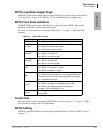
BPTU Loop Back Jumper Plugs
The BPTU PCB provides jumper plugs for loop back testing. Loop back tests are described in
“Loop-back Test” on page 7-34. See Table 7-2 for switch settings for Loop Back tests.
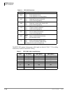
BPTU Front Panel Indicators
The BPTU PCB provides seven LED indicators to show the status of BPTU: Busy or Idle
condition, Alarm status, and Synchronization status.
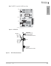
See Table 7-4 for the function of each status LED. Figure 7-3 on page 7-5 shows the LED
locations.
Ferrite Core
Install the Ferrite core provided with the BPTU PCB, as shown in Figure 7-7 on page 7-13. This
core is needed to comply with FCC requirements.
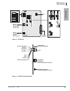
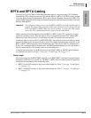
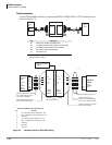
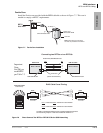
BPTU Cabling
The BPTU and RPTU PCBs use the same cabling methods. Refer to “BPTU and RPTU Cabling”
on page 7-11.
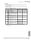
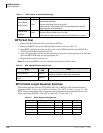
Table 7-4 BPTU LED Functions
BPTU LEDs Indication
FSYNC Frame Sync error indication. This LED is not mounted.
MFSYNC
Multi-frame Sync error indication (same with FSYNC)
On = No frame synchronization status
Off = Frame synchronization status
BALM/AIS
AIS indication
On = BPTU is receiving AIS
Off = BPTU is not receiving AIS
YALM/RAI
RAI indication
On = BPTU is receiving RAI
Off = BPTU is not receiving RAI
LOS
Signaling Loss indication
On = BPTU is not receiving T1 signals
Off = BPTU is receiving T1 signals
BSY
Busy state indication
On = One or more B-channels are in use. Also when BPTU does
not receive far end 1.544 mbs carrier signal, BSY is on steady.
Off = All B-channels are idle
PSYNC
Primary synchronization indication
On = BPTU is assigned as the secondary timing PCB.
Off = BPTU is not assigned as the CLK timing PCB
Flashing = BPTU is extracting T1 CLK
SSYNC
Secondary synchronization indication
Not mounted