


Strata CTX Configuration
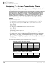
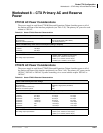
Worksheet 7 – System Power Factor Check
2-42 Strata CTX I&M 06/04
Worksheet 7 – System Power Factor Check
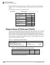
The Strata CTX power supply was engineered for maximum cost efficiency to provide power for
the most configurations. Because of this design, there are some -24VDC power limitations for
telephone option hardware.
Each telephone/device and PCB has been assigned Power Factors (PFs) that reflect the amount of
power supply resources they consume. The Power Supply Unit has also been assigned Power
Factors that reflect how much power it can supply. To make sure the cabinet power supply is
operating within its limit, it is necessary to add up the PFs of each telephone/device and PCB
installed in each cabinet to verify that their total PFs do not exceed the Power Supply PF.
Use the worksheets on pages 2-44~2-45 to calculate that each cabinet’s PF is within limits.
Important!
Power Factor Considerations:
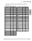
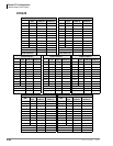
• The individual PCB and telephone power factors can be found on pages 2-43 and 2-44.
• The sum of all PCB and telephones –24VDC PFs in a given cabinet cannot exceed:
85 for CTX670
45 for CTX100
• The sum of all PCB +5VDC PFs in a given cabinet cannot exceed:
40 for CTX670
20 for CTX100
Telephones do not have +5VDC PFs.
• If a cabinet PF is exceeded it is necessary to reconfigure the cabinet to meet PF limits.
• If a cabinet’s Power Factor is exceeded, cabinet or connected peripherals may malfunction
during ringing or voice paging, whereas normal operation will occur for idle telephones.
• The Strata CTX100 and CTX670 power supplies provide a PF alarm LED and reset button. If
this LED is on, reset it with the reset button. Then recheck the cabinet PFs to make sure they
are within limits.
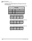
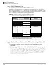
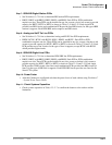
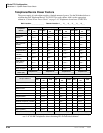
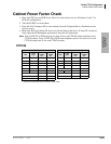
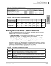
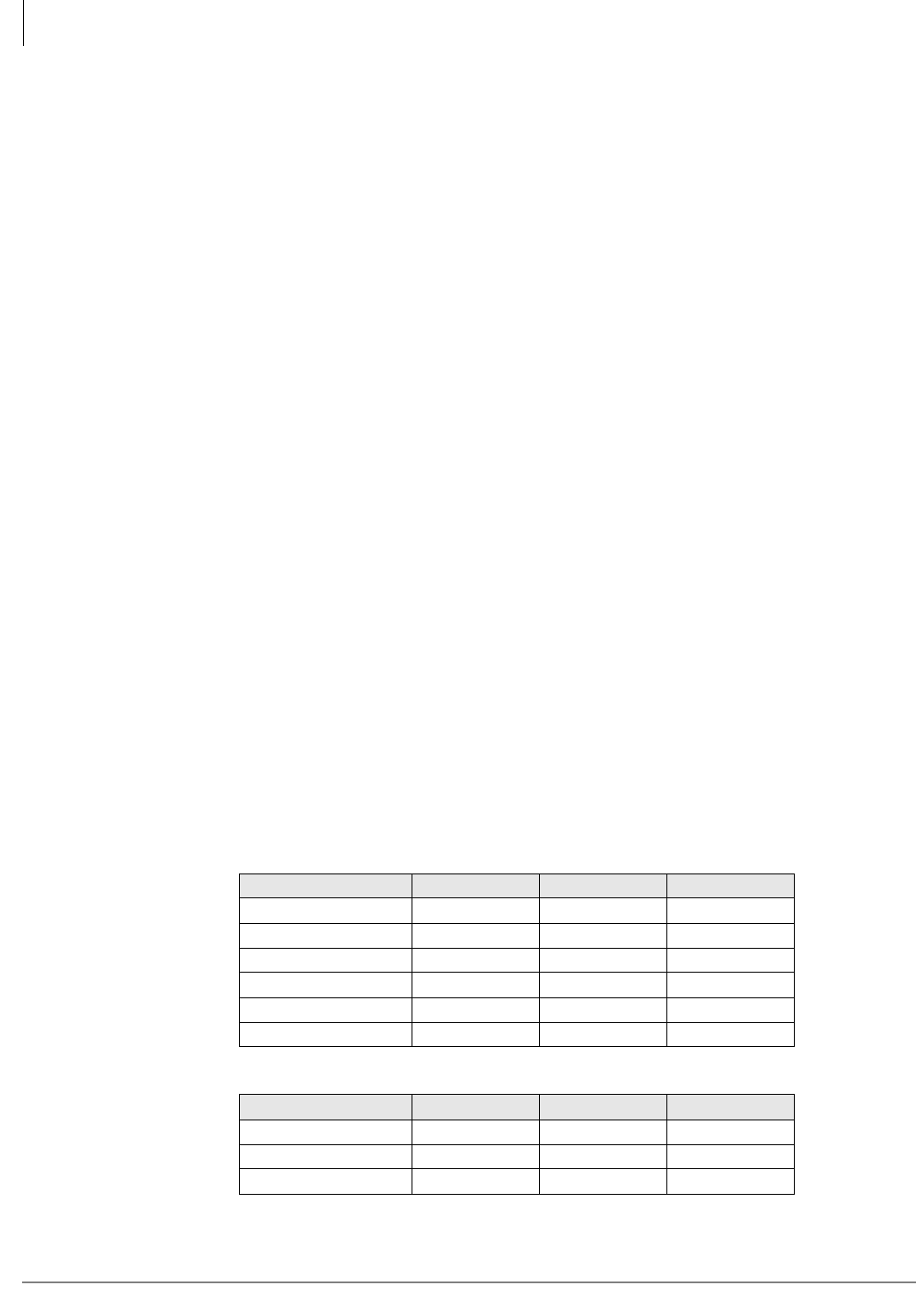
PCB Power Factor calculation examples are shown in Tables 2-56 and 2-57.
Table 2-56 Strata CTX Base Cabinet Example
PCB Quantity +5VDC PF -24VDC PF
PDKU 2 1.6 0.6
RBSU + RBSS 1 3.1 0.3
RCOU + RCOS 1 3.6 4.0
BBCU 1 4.5 2.0
BECU 1 4.5 2.0
Total 6 17.3 8.9
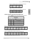
Table 2-57 Strata CTX Expansion Cabinet Example
PCB Quantity +5VDC PF -24VDC PF
RBSU + RBSS 1 3.1 0.3
RCOU + RCOS 1 3.6 4.0
Total 2 6.7 4.3