


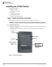
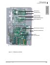
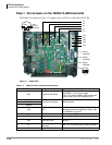
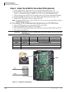
CTX28 Installation
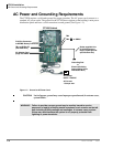
AC Power and Grounding Requirements
Strata CTX I&M 06/04 1-5
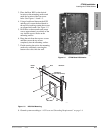
CTX28 Installation
AC Power Ground Test
Test the “wire ground” for continuity by either measuring the resistance between the TB3 terminal
(earth ground) on the GMAU and a metal cold water pipe (maximum: 1 ohm), or by using a
commercially available earth ground indicator. If neither procedure is possible, perform the
following earth ground test procedure.
³ To perform the earth ground test procedure
1. Obtain a suitable voltmeter, and set it for a possible reading of up to 250VAC.
2. Connect the meter probes between the two main AC voltage terminals (white and black wires)
on the wall outlet. The reading obtained should be between 100~125VAC.
3. Move one of the meter probes to TB3 terminal (green wire ground). Either the same reading or
a reading of zero volts should be obtained.
4. If the reading is zero volts, leave one probe on the ground terminal and move the other probe to
the second voltage terminal.
CAUTION! If a reading of zero volts is obtained on both voltage terminals (white wire to
TB3 wire, black wire to TB3 wire), the outlet is not properly grounded. Omit
Steps 5 and 6, and see following CAUTION!
5. If a reading of zero volts on one terminal, and a reading of 100~125VAC on the other terminal
is obtained, remove both probes from the outlet.
6. Set the meter to the “OHMS/Rx1” scale. Place one probe on the TB3 ground terminal, and the
other probe on the terminal that produced a reading of zero volts. The reading should be less
than one ohm.
CAUTION! If the reading is more than one ohm, then the outlet is not adequately
grounded. If the above tests show the outlet AC voltage is not in range or is
not properly grounded, the condition should be corrected (per Article 250 of
the National Electrical Code) by a qualified electrician before the system is
connected.
WARNING! Hazardous voltages that may cause death or injury are exposed during the
following test. Use great care when working with AC power line voltage.
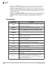
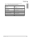
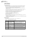
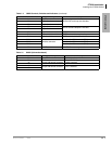
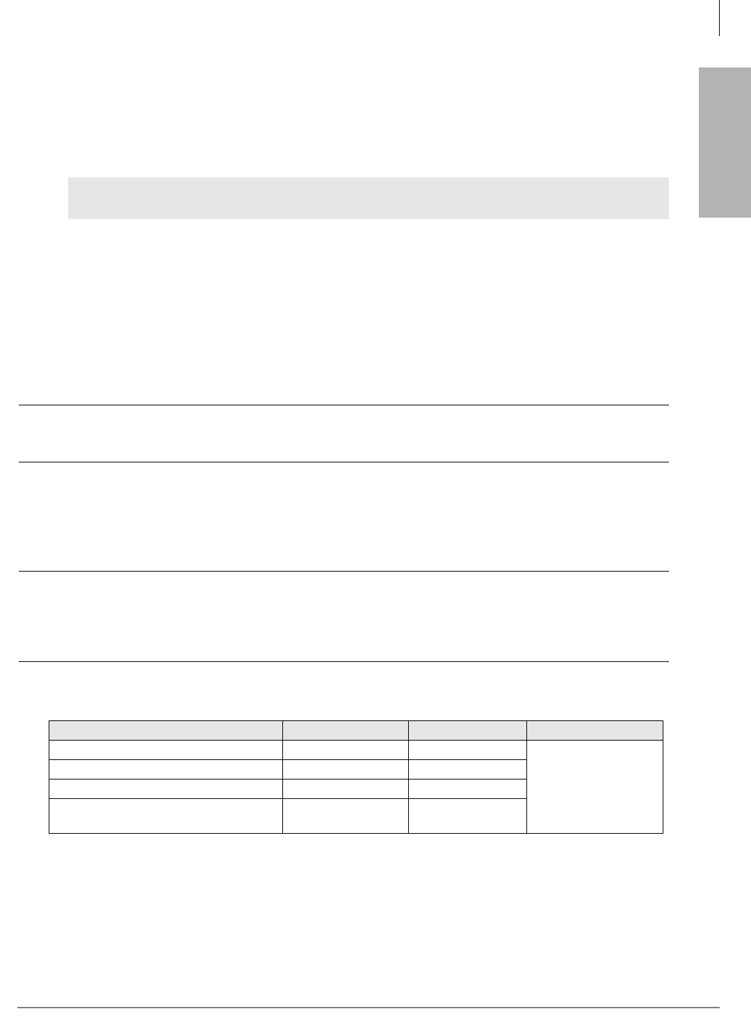
Table 1-2 Grounding Wiring Summary
Grounding Requirement From To Description
System connects to earth ground Earth ground TB3 on GMAU
Less than 1 ohm
FG of HPFB-6 connect to GMAU HPFB-6 FG Screw TB1 on GMAU
HPFB-6 Ground Feed TB1 on GMAU TB3 on GMAU
GETS connects green ground wire to
GMAU
GETS ground wire TB2 on GMAU