


Peripheral Installation
Power Failure Options
Strata CTX I&M 06/04 12-25
Peripheral Installation
Power Failure Options
In the event of a power failure, Strata CTX uses these options:
Reserve Power
For information on the Reserve Power Option, see Chapter 1 – Installation.
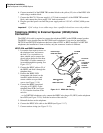
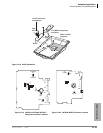
Power Failure Transfer Unit
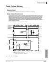
An optional Power Failure Transfer Unit (DPFT) can be installed that automatically connects up to
eight selected CO lines directly to designated standard telephones in the event of a power failure.
The DPFT enables normal operation of the selected CO lines and standard telephones when the
system is in service. When power is restored, each telephone is independently reconnected to
system standard telephone circuit ports after it is finished with its direct CO line call. The DPFT is
normally installed on the MDF.
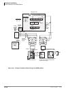
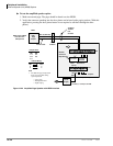
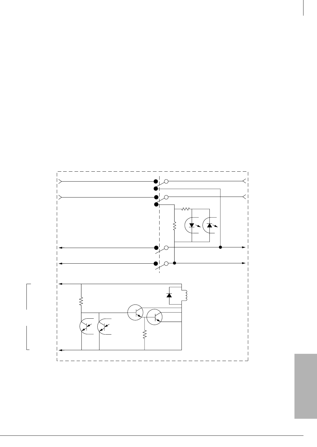
Figure 12-25 provides a circuit diagram of the DPFT.
Figure 12-25 DPFT Circuit Diagram
J2-26
J2-1
J1-26
J1-1
Relay
J1-25
J1-50
J1-2
J1-27
J2-2
J2-27
Telephone Current
Detector
To TEL-T1
To TEL-R1
To CO-T1
To CO-R1
To RSTU/PSTU-T1
RDSU/RSTS
To RSTU/PSTU-R1
RDSU/RSTS
To RCOU/PCOU-T1
To RCOU/PCOU-R1
DG (Input)
-24V (Input)
RSTU or PSTU
Control
1498
Notes
• Representation of first of eight circuits.
• Conditions shown with AC power (-24VDC) off.