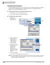
PCB Installation
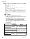
PDKU2 – Digital Telephone Interface Unit
Strata CTX I&M 06/04 6-19
PCB Installation
PDKU2 – Digital Telephone Interface Unit
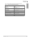
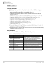
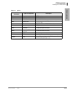
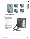
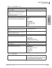
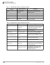
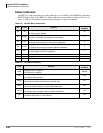
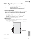
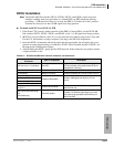
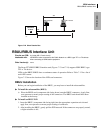
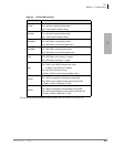
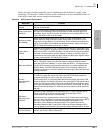
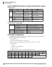
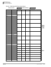
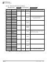
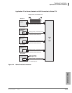
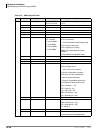
Circuits per PCB:
eight digital telephone circuits
Interfaces with:
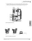
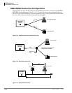
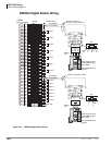
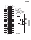
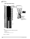
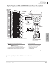
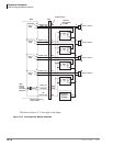
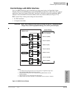
digital telephones (with or w/o ADM) (See Notes under Hardware Options)DDSS
console (circuit 8 only)
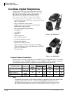
cordless digital telephones (DKT2004-CT, DKT2104-CT)
DKT2001 single line digital telephones
Older Version(s):
PDKU1 (identical to PDKU2 except it does not support continuous DTMF tones
w/DKT2000-series telephones, DIUs can only be connected to circuits 1~7)
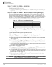
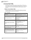
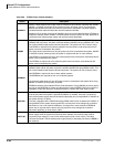
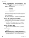
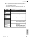
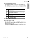
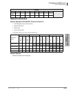
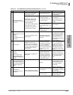
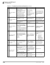
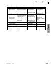
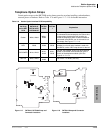
PDKU2 Hardware Options
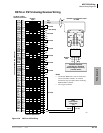
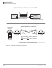
PDKU2 does not have to be configured for any option. Refer to Chapter 11 – Station Apparatus for
instructions on how to connect digital telephones, DADMs, and DDSS consoles to the PDKU2.
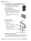
Refer to Chapter 12 – Peripheral Installation for instructions on connecting Door Phones
(DDCBs).
Notes
• BPCI, RPCI-DI and PDIU-DI are not supported on Strata CTX.
• With the DKT3000-series telephones, limitations are 16 (not 24) character LCD display,
Spdial and LCD Feature buttons don’t work and the BPCI cannot be used
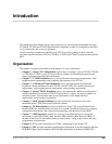
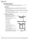
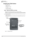
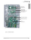
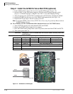
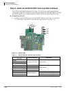
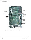
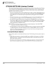
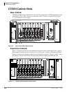
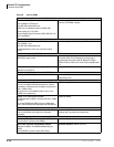
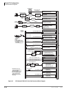
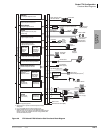
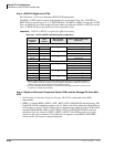
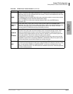
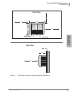
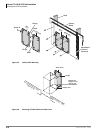
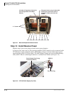
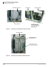
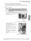
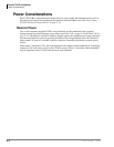
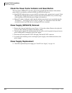
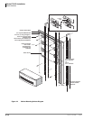
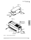
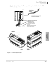
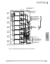
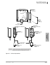
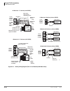
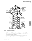
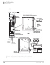
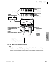
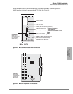
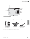
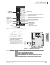
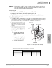
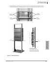
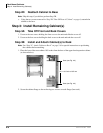
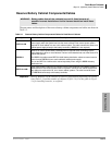
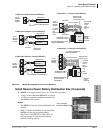
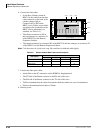
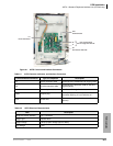
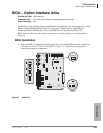
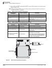
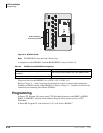
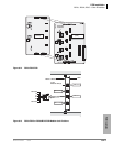
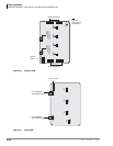
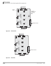
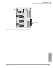
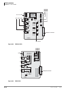
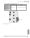
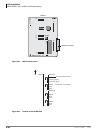
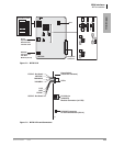
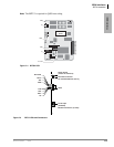
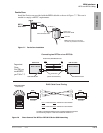
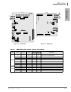
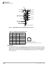
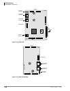
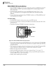
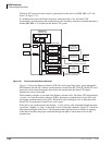
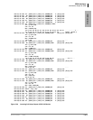
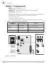
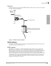
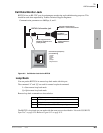
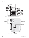
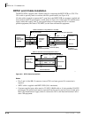
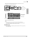
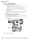
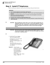
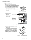
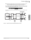
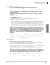
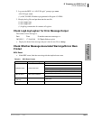
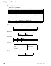
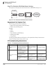
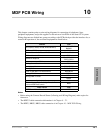
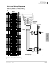
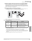
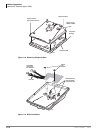
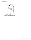
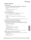
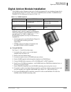
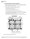
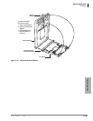
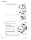
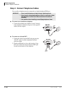
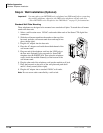
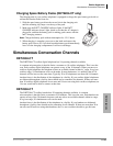
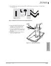
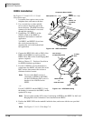
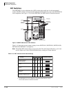
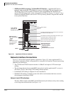
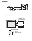
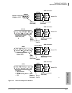
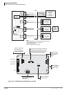
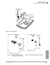
There are no controls or indicators on the PDKU (Figure 6-13).
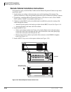
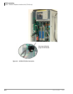
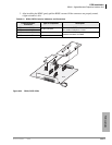
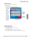
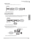
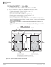
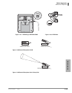
PDKU2 Installation
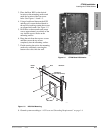
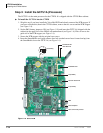
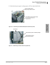
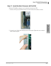
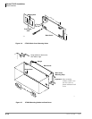
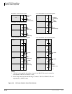
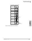
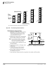
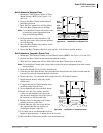
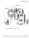
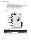
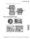
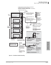
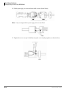
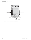
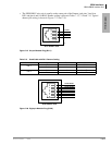
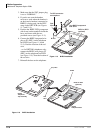
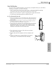
1. Insert the PDKU2 (component side facing right) into the appropriate slot, and apply firm, even
pressure to ensure proper mating of connectors.
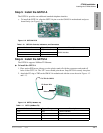
2. After installing the PDKU, gently pull the PCB outward. If the connectors are properly mated,
a slight resistance is felt.
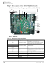
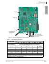
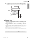
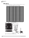
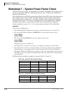
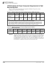
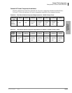
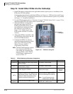
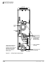
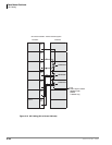
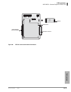
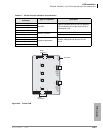
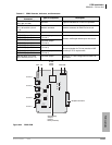
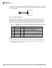
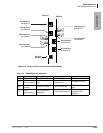
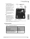
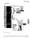
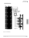
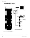
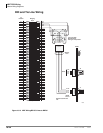
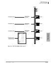
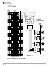
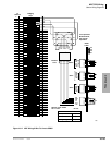
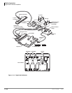
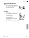
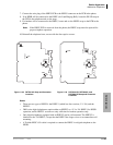
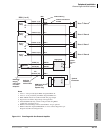
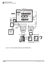
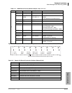
Figure 6-13 PDKU2 PCB
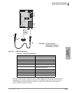
Backplane Connector
50-Pin Female Amphenol Connector
5807