


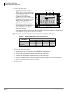
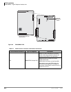

PCB Installation
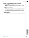
ASTU – Standard Telephone Interface Unit (CTX100 only)
6-4 Strata CTX I&M 06/04
ASTU – Standard Telephone Interface Unit
(CTX100 only)
Circuits per PCB:
two standard telephone circuits
maximum number of ringers per circuit is three
Interfaces with:
standard telephones (no message waiting)
other single-line devices
alternate BGM source
FAX machine
voice mail devices
Older Version(s):
none
The ASTU works with the CTX100 Base system with R1.3 and higher software. It provides two
standard telephone ports and connects to a unique slot on the side of the CTX100. It does not
occupy one of the universal slots.
ASTU Installation
1. Turn the power to the CTX100 off (press the DC power switch) and unplug the system.
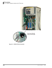
2. Remove the front and left-side covers from the CTX100.
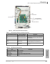
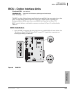
3. Refer to Figure 6-1 and Table 6-2. Make sure the SW2 switch is in the “Mu law” position for
the U.S. and Canada.
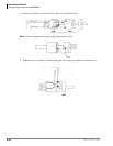
4. Align the holes on the ASTU with the white plastic posts on the left side of the CTX100 Base
Cabinet. Firmly press the ASTU onto the posts to attach it to the CTX100. Make sure that you
can still reach all attached cables and wires.
5. Slip the spade of the FG1 (green wire) under the grounding screw on the CTX100 and tighten
the screw.
6. From the CTX100, locate the multi-colored five wire cable (white connector) and plug it into
the P1 connector on the ASTU.
7. On the ASTU, locate the 10-wire P2 connector cable and plug it into the front of the ACTU
processor PCB on the CTX100 (see Figure 6-2). Press firmly so that both black flip-locks snap
shut. (To remove, flip up the front and back locks.)
8. Connect the standard telephone(s) or devices to J1 and J2 on the ASTU.
9. Plug in the CTX100 power and turn on the DC power switch in the front of the CTX100. If
everything seems to be working, re-attach the outside covers.
10. Power down and power up the CTX100 and the system will automatically recognize the ASTU
in virtual slot 09. Otherwise, you can use CTX WinAdmin R1.3 or later to assign the ASTU in
the 0109 position.
ASTU1 Wiring
1. 300 ohms loop resistance max., including the telephone or other devices DC off-hook
resistance.
2. ASTU requires secondary protectors with standard voltage for outside wiring. See Table 6-1 for
electrical characteristics.