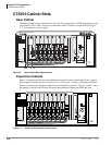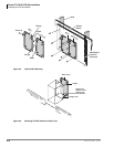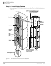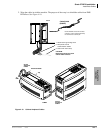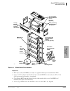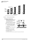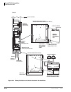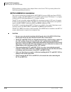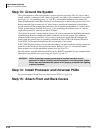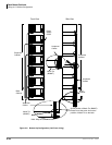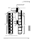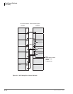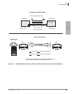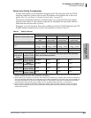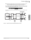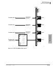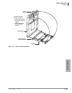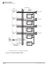
Rack Mount Cabinets
Power Supply Unit (BRPSU672A)
5-28 Strata CTX I&M 06/04
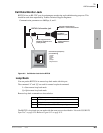
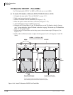
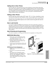
Power Supply Unit (BRPSU672A)
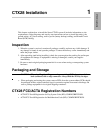
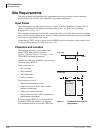
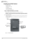
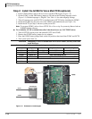
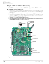
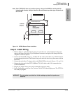
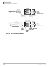
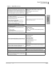
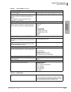
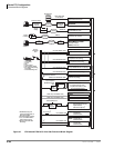
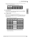
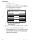
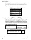
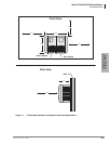
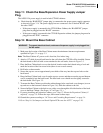
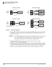
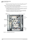
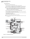
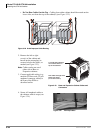
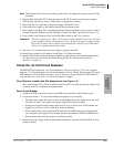
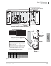
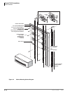
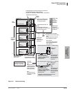
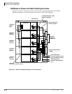
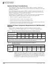
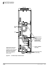
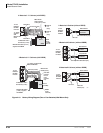
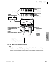
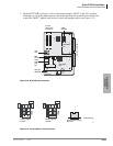
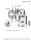
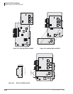
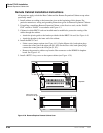
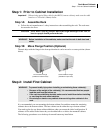
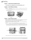
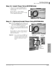
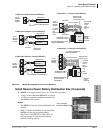
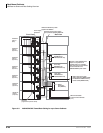
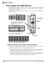
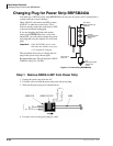
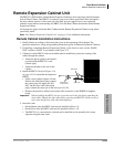
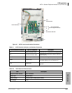
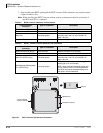
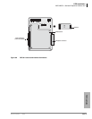
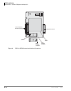
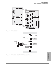
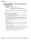
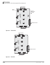
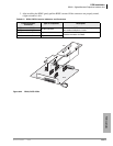
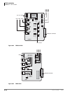
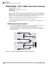
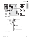
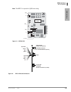
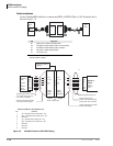
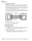
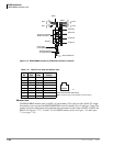
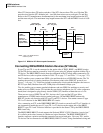
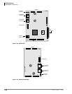
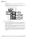
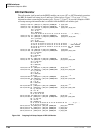
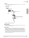
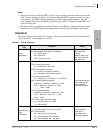
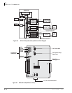
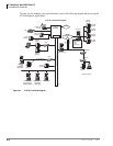
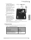
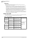
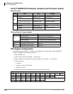
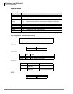
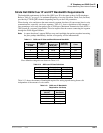
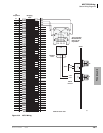
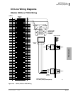
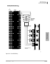
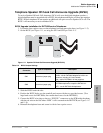
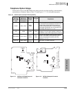
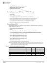
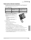
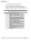
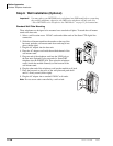
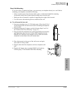
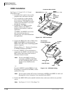
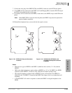
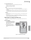
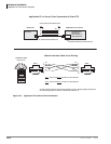
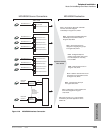
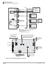
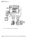
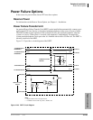
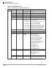
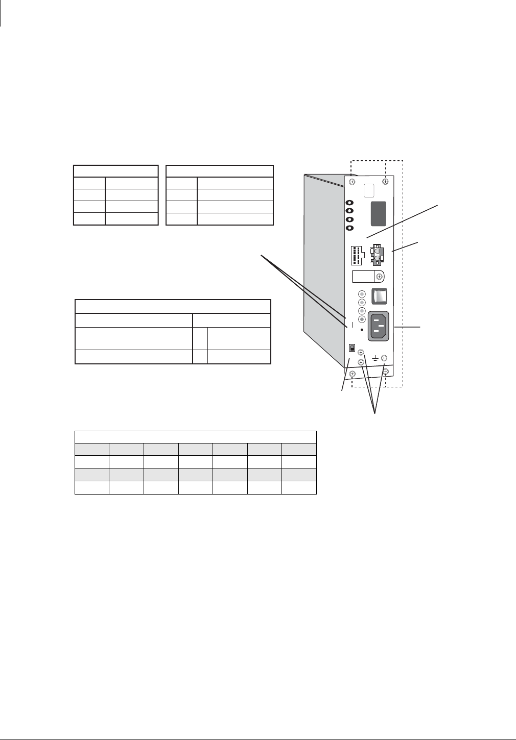
The BRPSU672A Power Supply Unit (shown below) comes factory installed in each Rack Mount
Base and Expansion Cabinet. It furnishes power to all of the stations and some of the peripherals
that interface with the cabinet.
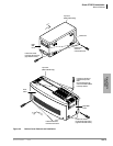
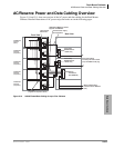
The BRPSU672A automatically detects and adjusts for the type of AC voltage (120/208/240) to
which it is connected.
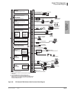
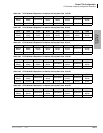
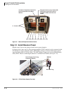
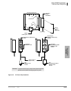
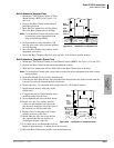
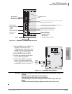
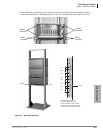
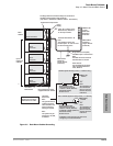
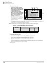
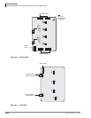
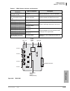
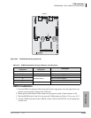
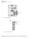
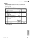
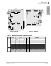
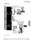
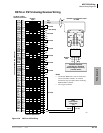
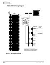
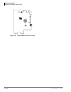
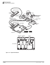
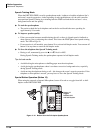
Figure 5-12 Power Supply Unit (BRPSU672A)
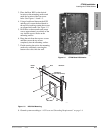
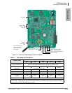
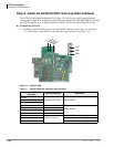
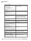
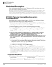
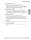
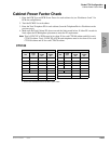
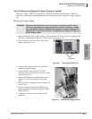
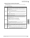
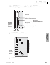
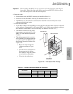
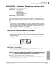
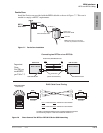
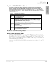
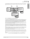
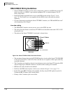
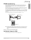
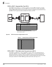
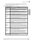
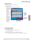
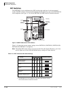
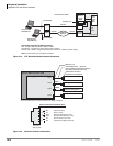
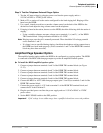
Check the Power Factor Indicator and Reset Button
The front panel of BRPSU672A provides a Power Factor LED and Reset button. If the cabinet
power factor is exceeded by overload of PCBs, the PF LED will turn on.
³ If the PF LED indicator turns on, press the PF reset button with a pointed tool or pencil. If the
PF LED turns off and does not turn on again it may have been turned on by a current surge
while installing a PCB while the power supply was turned-on.
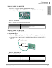
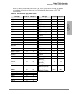
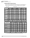
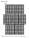
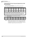
³ When a PF alarm is indicated, check that the cabinet power factor is not exceeded using the
“Worksheet 7 – System Power Factor Check” on page 2-42. If the Power factor has been
exceeded relocate any PCBs that are causing the PF to be exceeded.
7000
BATT
EXP
BASE
FG
POW
+5V
-5V
P. F.
RESET
POWER ON
OFF
-24V1
-24V2
-24V3
-24V4
AC IN
DC OUT
FG
+
-
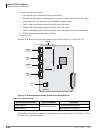
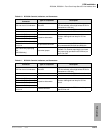
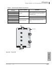
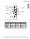
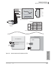
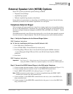
DC Voltage
Connector Jack
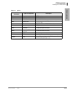
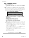
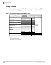
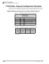
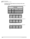
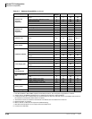
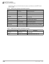
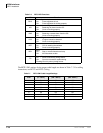
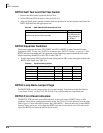
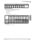
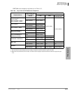
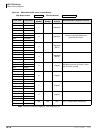
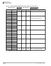
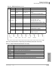
DC Voltage Specification
+5V (+4.5 ~ +5.5), 4.0 amps
-5V (–4.5 ~ –5.5), 0.8 amps
Expansion Cabinet only
-24V (–26.3 ~ –27.8), 6.0 amps
BATT (Volts)
+
–
0
–26.3 ~ –27.8
1. Back Plane DC Voltage Plug must be plugged
into Power Supply when checking voltages.
2. On BRPSU672, the BATT output is 0 volts
unless connected to good batteries.
Power Factor (PF) alarm LED indicates
the cabinet PF was exceeded. Correct
the problem and press the RESET
button to clear the alarm.
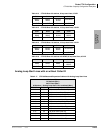
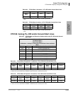
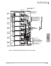
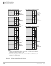
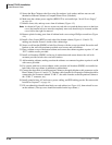
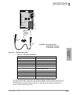
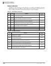
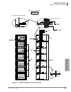
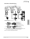
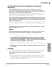
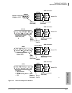
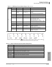
24V Circuit Breaker Assignments:
24V-1
24V-2
24V-3
24V-4
EXP. Cabinet
24V-1
24V-2
24V-3
24V-4
S101, S102
S103, S104
S105, S106
S107, S108
S_01, S_02
S_03, S_04
S_05, S_06, S_07
S_08, S_09, S_10
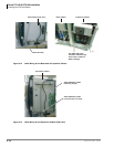
Base Cabinet
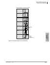
Expansion/
Base Switch
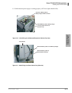
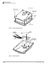
FG Frame
Ground Screws
Battery Cable
Connector
AC Power
Cord Jack
2
Mounting Holes
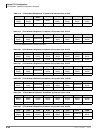
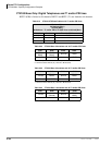
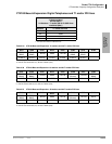
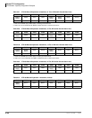
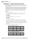
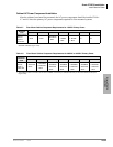
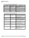
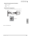
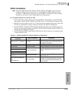
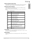
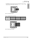
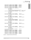
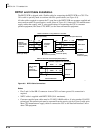
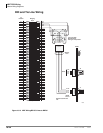
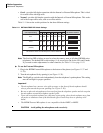
DC Voltage Connector Plug Pin Wires
Yellow Blue White Green Green Green Red
-24 -5 +5 0 0 0 +5
Yellow Yellow Yellow Green Green Green Red
-24 -24 -24 0 0 0 +5