


Strata CTX100-S/CTX100 Installation
Installing the CTX100 Cabinet
3-16 Strata CTX I&M 06/04
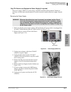
4. Replace the power supply if the fuse continues to blow and a defective PCB or short cannot be
found. See “Step 7D: Remove and Replace the Power Supply (if required)” on page 3-17.
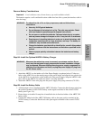
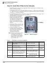
Step 7C: Check the Power Factor Indicator and Reset Button
The front panel of APSU112 provides a Power Factor LED and Reset button. If the cabinet power
factor is exceeded by overload of PCBs, the PF LED will turn on.
³ If the PF LED indicator turns on, press the PF reset button with a pointed tool or pencil. If the
PF LED turns off and does not turn on again it may have been turned on by a current surge
while installing a PCB while the power supply was turned-on.
³ When a PF alarm is indicated, check that the cabinet power factor is not exceeded using
“Worksheet 7 – System Power Factor Check” on page 2-42. If the Power factor has been
exceeded relocate any PCBs that are causing the PF to be exceeded.
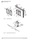
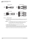
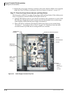
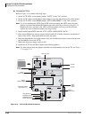
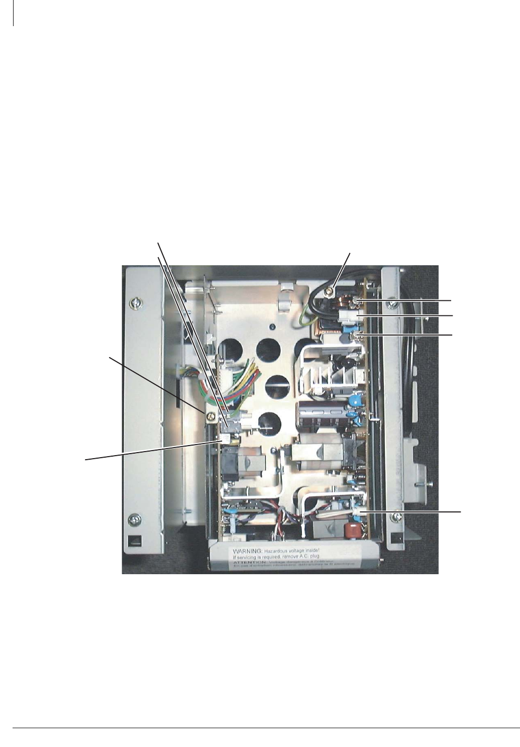
Figure 3-14 Power Supply Connectors Top View
AC Fuse
AC Fuse
AC Cord Third Wire Ground Screw
AC-IN Connector
EXP
Expansion
Cabinet
Power Supply
Jumper
Connector
V1-24 Volt Circuit
Breakers:
Motherboard
FG Wire Screw
V2
BASE
Base Cabinet
Power Supply
Jumper
Connector
5997