


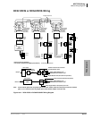
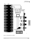
MDF PCB Wiring
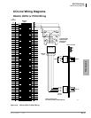
Station Wiring Diagrams
Strata CTX I&M 06/04 10-21
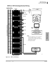
MDF PCB Wiring
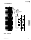
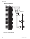
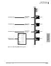
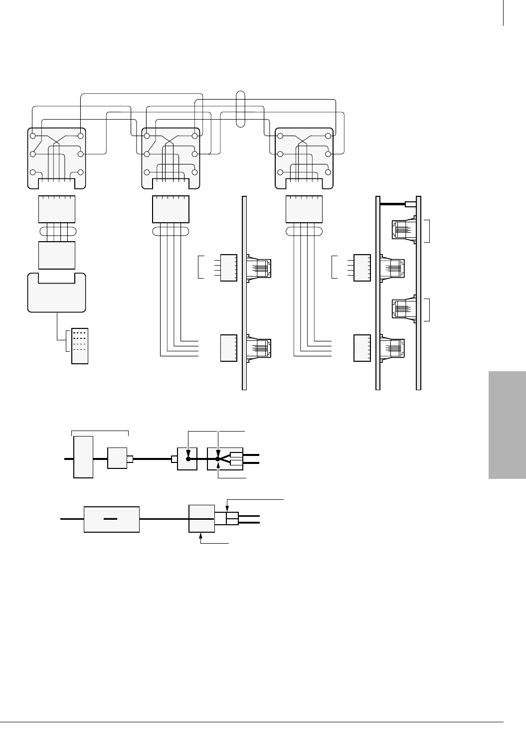
RCIU1/RCIS or RCIU2/RCIS Wiring
GN
654321
Y
BL
R
BK
W
2345
Modular
Cords
R1
R2
T1
T2
Dealer Supplied
Modular Block,
625-Type or
Equivalent
(See Notes)
R2
R1
T1
T2
5
4
3
2
CKT 7&8
1-61-6
CKT 3&4
CKT 5&6
RCIU RCIS
CKT 1&2
1
2
3456
Same
Same
Same
R4
R3
T3
T4
5
4
3
2
1
2
3456
GN
654321
Y
BL
R
BK
W
23452345
4-Wire
Modular
Cord
4-Wire
Modular
Cord
Telco
RJ14C
Modular Jack
T1
T2
Dealer Supplied
Modular Block,
625-Type or
Equivalent
(See Notes)
Bridging Jumper Wires
R1
R1
R2
R2
GN
654321
Y
BL
R
BK
W
T1
T2
Dealer Supplied
Modular Block,
625-Type or
Equivalent
(See Notes)
R2
R1
T1
T2
T1
R1
T2
R2
LINE X
LINE Y
Telco
RJ21X
5
4
3
2
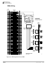
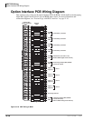
Network Jack: RJ14C/RJ21X
FIC: 02LS2 (Loop Start) OR 02GS2 (Ground Start)
6-16-1
6-16-1
CKT 3&4
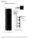
RGLU/RCOU/RCOS/PCOU/TCOU
Pin-outPin-out
CKT 1&2
1
2
3456
Same
R4
R3
T3
T4
5
4
3
2
1
2
3456
Network
RJ21X
Network
RJ14C
RJ14C
Telco Jacks
Telco RJ21X
4-Wire
Modular
Cord
Installer Cross Connect Customer
Supplied Modular Jacks
Duplex Modular Jack (AA-104A-4 or Equivalent)
RCOU 4-Wire Modular Cord
1
4-Wire Single Modular Jack (RJ14C) from Telco
RCIU/RCIS 4-Wire Modular Cord
2
RCOU 4-Wire Modular Cord
1
4-Wire Connector (267A2 Or Equivalent)
RCIU/RCIS 4-Wire Modular Cord
2
1608
Note 4-wire modular jacks such as graybar part number AA-104A-4 could be used in place of the two modular
jacks; or, a T-connector such as graybar part number 267A2 Adaptor could be used.
Figure 10-12 RCIU1/RCIS or RCIU2/RCIS MDF Wiring Diagram