


ISDN Interfaces
RBUU/RBUS Interface Unit
Strata CTX I&M 06/04 7-27
ISDN Interfaces
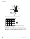
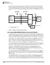
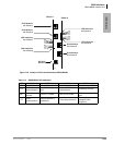
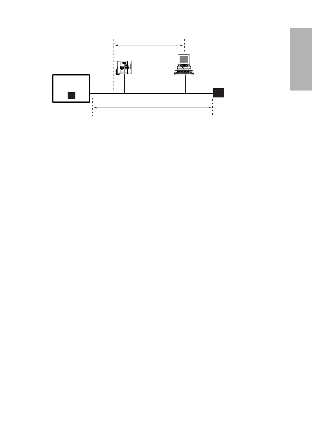
Figure 7-22 Short Passive Bus
RBUU/RBUS Interface Unit
Circuits per PCB:
2 circuits (2B + D each circuit)
Interfaces with:
ISDN BRI U when connected to the Public Network or a BRI U-type TE-1 or TA devices
when connecting to ISDN station equipment
Older Version(s):
none
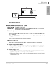
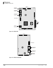
The Strata CTX RBUU/RBUS interface unit (Figures 7-23 and 7-24) supports ISDN BRI U-type
TE1 or TA devices.
LEDs on the RBUU/RBUS show a continuous status of operation. Refer to Table 7-12 for a list of
each LED’s status.
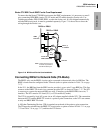
Figure 7-25 shows the location of the LEDs and connectors.
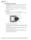
RBUU Installation
Before you can begin installation of the RBUU, you may have to install the subassemblies.
³ To install the subassemblies (RBUS)
³ Place the RBUS card (component side facing down) onto the RBUU connectors. Apply firm,
even pressure to ensure proper seating of the connectors. The RBUS card should have been
installed at the factory.
³ To install an RBUU PCB
1. Insert the RBUU (component side facing right) into the appropriate expansion unit slot and
apply firm, even pressure to ensure proper seating of connectors.
2. After installing the RBUU, gently pull the PCB outward. If the connectors are properly seated,
a slight resistance is felt.
5438
TR
640'
490'
RJ45
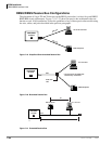
RBSU/RBSS
NT-Mode
TR
ISDN Telephone TE-1 PC Card