


Strata CTX I&M 06/04 8-1
T1
T1 8
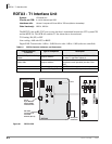
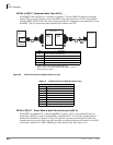
This chapter covers the RDTU T1/DS-1 interface for the Strata CTX systems. It contains
information about the RDTU3 and RDTU1/2. The RDTU3 is a replacement for the RDTU1 and 2.
Note “RDTU” refers to all RDTU (1, 2 or 3) PCBs. When a distinction is required, the exact
numbered term, such as “RDTU3” is used.
Program Channels
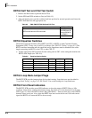
The RDTU PCB provides T1/DS-1 interface for up to 24 channels on the Strata CTX. Each
channel can be individually set for loop start, ground start, Tie, or DID line operation (voice only,
not data lines). Each RDTU can be set in system programming to activate (1~8), (1~16), or (1~24)
channels (lines). Fractional increments of 4, 12, and 20 are also possible but the RDTU still
assigns 8, 16, or 24 channels respectively in system software.
Example: If only 12 channels of fractional T1 are used, assign RDTU as a 16 channel RDTU. The
system assigns 16 CO lines to the RDTU even though only 12 CO lines are used.
Select Slot Assignments
RDTU PCBs can be installed in a Strata CTX to provide up to 264 lines (max). RDTU PCBs can
be installed in any CTX cabinet, except remote CTX cabinets driven with RRCU cards. RDTU
PCBs must be placed in designated slots in each of the Strata CTX cabinets. (See “Worksheet 5:
Strata CTX100 Cabinet Slots” on page 2-26 and “Worksheet 6: Strata CTX670 Cabinet Slots” on
page 2-37.)
If an RDTU is installed in a cabinet (in some cases one slot to the right of the RDTU may not be
used in that cabinet) the number of unusable slots in a cabinet depends on which slot the RDTU
occupies and how many lines (16 or 24) the RDTU is programmed to provide.