


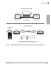
T1
RDTU3 - T1 Interface Unit
8-2 Strata CTX I&M 06/04
RDTU3 - T1 Interface Unit
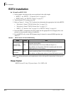
System:
CTX100 & 670
Circuits per PCB:
8, 16, 24 channels per PCB
Interfaces with:
Ground / Loop start CO lines DID or TIE lines (Wink or Immediate)
Older Version(s):
RDTU1, RDTU2
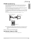
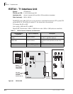
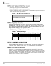
The RDTU3A has an RS-232C port to trace data that is transmitted between the CTX system CPU
and the RDTU3A. This PCB also enables T1 line alarm data to be monitored.
T1 Framing: D4 (SF) or ESF
Line cording: AMI with ZCS or B8ZS
Digital PAD: Transmit side +3dB to -15dB. Receive side +3dB to -15dB (software controlled)
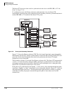
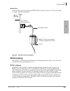
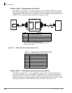
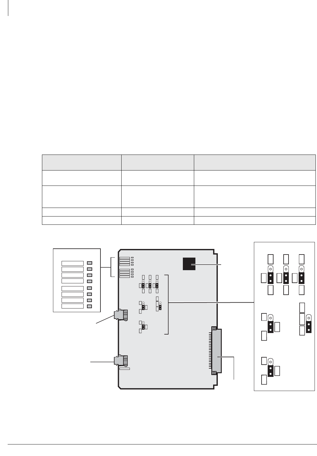
Figure 8-1 RDTU3 PCB
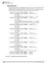
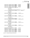
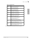
Table 8-1 RDTU3 Controls, Indicators, and Connectors
Control/Indicator/
Connector
Type of Component Description
SW4~SW6 Equalizer Setting
Switch
Jumper switches
Sets the line length between RDTU and CSUs
or other T1 (see also Table 8-6).
SW8, SW9 Jumper switches
Used for Self Test and CSU Test or for non-
loop back normal operation (see also Ta bl e
8-5).
SW10 3-terminal jumper plug See Table 8-3.
IC19 External ROM upgrade Provides external ROM option (see Table 8-3).
RS-232C
Connector for
Call Data
Monitor (RJ-12)
J1J2
6351
Backplane
Connector
OFF
EQ
ON
SW4
R28
OFF
EQ
ON
SW5
R28
OFF
EQ
ON
SW6
R28
O
F
F
LB
ON
SW8
C
P
U
ROM
SW10
O
F
F
LB
ON
SW9
RDTU3A
FSYNC
MFSYNC
BALM/AIS
YALM/RAI
LOS
BSY
PSYNC
SSYNC
MONITOR
Status/Alarm LEDs
FSYNC
MFSYNC
BALM/AIS
YALM/RAI
LOS
BSY
PSYNC
SSYNC
OFF
EQ
ON
SW4
R28
OFF
EQ
ON
SW5
R28
OFF
EQ
ON
SW6
R28
O
FF
LB
ON
SW8
C
P
U
ROM
SW10
O
FF
LB
ON
SW9
IC19
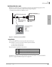
RJ-45
8-pin Modular
Network/CSU
Interface Jack