


Strata CTX
Configuration
Strata CTX Configuration
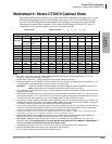
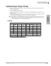
Worksheet 7 – System Power Factor Check
Strata CTX I&M 06/04 2-43
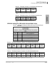
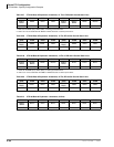
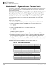
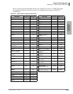
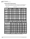
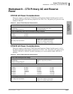
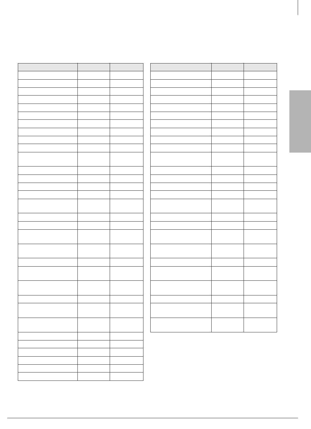
Table 2-58 shows the individual PCB +5VDC and -24VDC power factors. -24VDC PF numbers
for telephones and devices are shown on page 2-44; telephones do not require +5VDC PF
considerations.
Table 2-58 PCB and Power Supply Power Factors
PCB Type +5VDC PF -24VDC PF PCB Type +5VDC PF -24VDC PF
ACTU1, 2 1.1 0.5 RCIS1 0.3 0.1
ADKU 0.8 0.3 RCIU1, 2 0.7 0.2
AETS 0.2 0.1 RCIU2 0.7 0.2
ARCS 0.0 0.0 RCMS1 0.6 0.3
AMDS 1.3 0.5 RCOS1, 2 1.7 2.0
ASTU 0.3 0.5 RCOU (4 CO) 2.5 2.0
BCTU 8.5 3.4 RCOU + RCOS (8 CO) 3.6 4.0
BEXU 4.0 1.6 RCOU1, 2 1.9 2.0
BBCU1 4.5 2.0 RDDU1 2.6 7.0
BECU1 4.5 2.0 RDSU1 (-24VDC) 1.1 0.3
BEXS1 2.0 1.0
RDSU1 + R48S1
(-48VDC)
1.1 0.5
BBMS1 0 0 RDTU1, 2 1.8 1.0
BDKU1 0.8 0.3 RDTU3 0.2 0.6
BDKS1 0.4 0.15 REMU2/PEMU1 1.0 7.5
BIOU1 1.5 6.6 RGLU1, 2 2.1 2.5
BIPU-M2A, BIPU-M1A/
BIPU-Q1A
0.1 3.0 RMCU1 0.7 0.3
BPTU1 2.3 0.7 RPTU1, 2 2.6 1.0
BSIS1 1.0 0.5 RSTU1, 2, 3 (-24VDC) 1.4 0.5
BSTU1 (-24VDC) 1.4 1.0
RSTU1+ R48S
(-48VDC)
1.4 1.0
BSTU1 + R48S (-
48VDC)
1.4 2.3
RSTU2, 3 + R48S
(-48VDC)
4.0 2.3
BVPU1‘ 0.0 3.5 RRCU1 0.0 4.0
BWDKU 0.8 0.3
Stratagy iES32,
32 circuits
014
PCOU1, 2 1.9 2.0
Stratagy iES32,
16-circuits
014
PDKU1, 2 0.8 0.3 Stratagy IVP8 4.0 2.3
R40S1 0.0 2.8
Power Supply
APSU112 (CTX100)
(20.0) (45.0)
RBSS1 0.6 0.3
Power Supply
BPSU672 (CTX670)
(40.0) (85.0)
RBSS2 0.0 0.3
RBSU + RBSS 3.1 0.3
RBSU1 2.5 1.0
RBSU2 0.0 1.0
RBUS1 0.0 0.3
RBUU1 0.0 1.0