


Strata CTX670 Installation
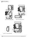
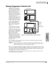
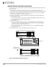
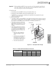
Remote Expansion Cabinet Unit
4-60 Strata CTX I&M 06/04
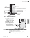
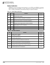
Status Indicators
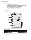
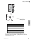
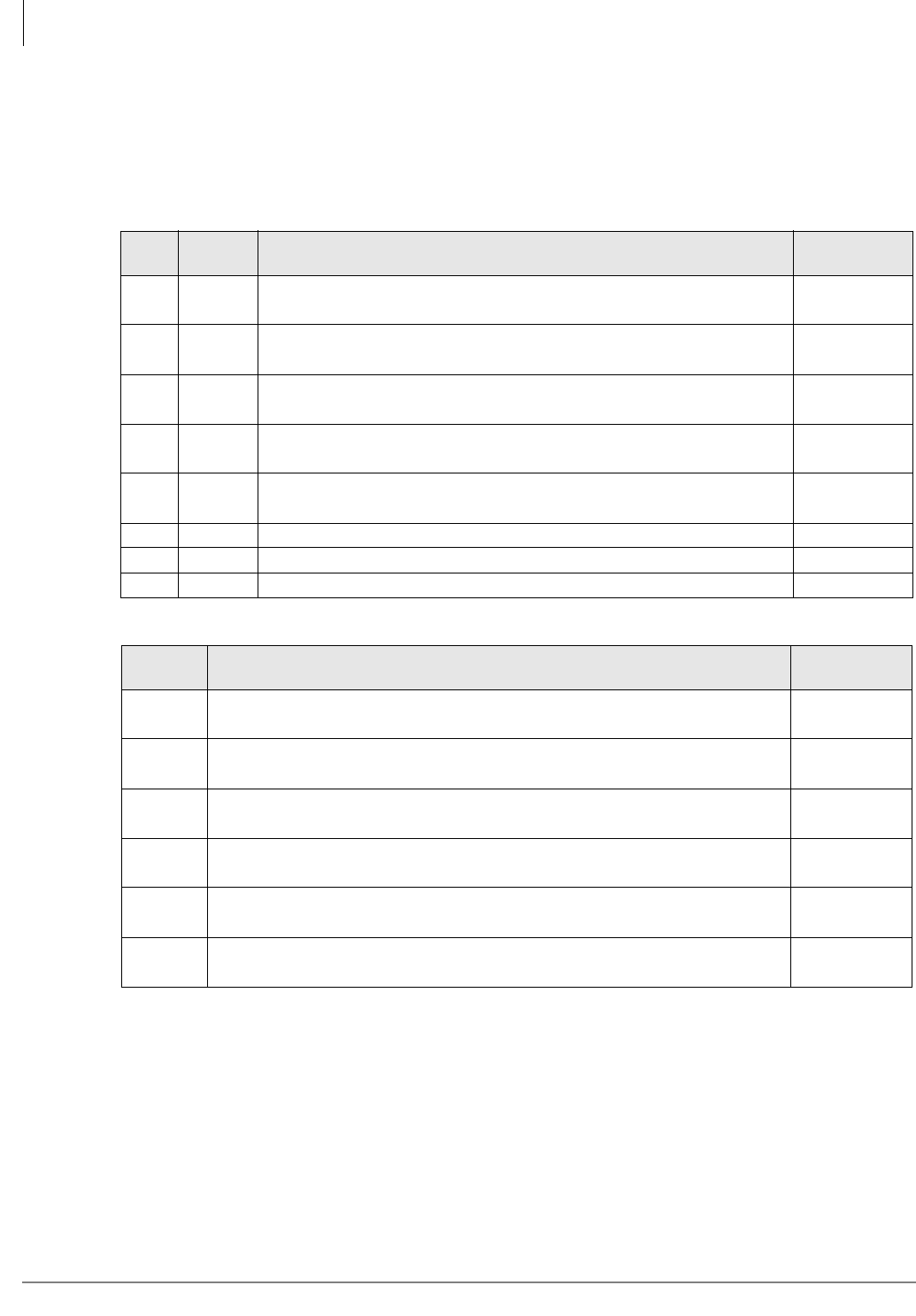
The RRCU1A card set provides two status indicators: a set of LEDs on the ROMS1A card and an
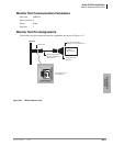
RS232C Monitor Port on the RRCU1A. Status indications are provided according to Tables 4-16
and 4-17. Binary Code Output is generated upon change of a reported condition.
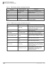
Table 4-16 RS-232C Binary Code Output
BIT Label Function
Normal
Condition
D0 SD
1: Optical signal not detected
0: Optical signal detected
0
D1 RDER
1: Code rule violation detected in received data
0: Code rule violation not detected in received data
0
D2 SYCF
1: Frame synchronization of received data not established
0: Frame synchronization of received data established
0
D3 SYCS
1: System synchronization between cabinets not established
0: System synchronization between cabinets established
0
D4 RST
1: Reset signal from CTU detected
0: Reset signal from CTU not detected
0
D5 Not Used 0
D6 Not Used 1
D7 Not Used 0
Table 4-17 LED Status Indications
LED Function
Normal
Condition
PWR
Blinking: Power is supplied
Off: Power is not supplied
Blinking
SD
On: Optical signal not detected
Off: Optical signal detected
Off
RDER
On: Code rule violation detected in received data
Off: Code rule violation not detected in received data
Off
SYCF
On: Frame synchronization of received data not established
Off: Frame synchronization of received data established
Off
SYCS
On: System synchronization between cabinets not established
Off: System synchronization between cabinets established
Off
RST
On: Reset signal from CTU detected
Off: Reset signal from CTU not detected
Off