


CTX28 Installation
Installing the CTX28 Cabinet
1-14 Strata CTX I&M 06/04
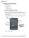
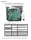
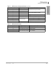
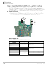
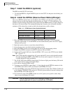
Step 3: Install the GCTU1A (Processor)
The GCTU1A is the main processor for the CTX28. It is shipped with the CTX28 Base cabinet.
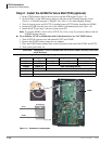
³ To install the GCTU1A into the CTX28
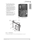
1. Skip this step if you have installed a Voice Mail PCB and already removed the PCB stopper. If
you have not done this, then in the CTX28 cabinet, remove the two screws and the PCB stopper
(see Figure 1-8).
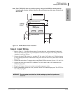
2. Set the P601 battery jumper to ON (see Figure 1-10) and insert the GCTU1A (shipped with the
cabinet) in the upper slot of the GMAS sub-motherboard (see Figure 1-6). Place it next to the
guide rail of the PCB stopper (see Figure 1-8).
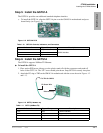
3. Secure the PCB stopper with the original two screws.
4. Insert the SmartMedia card (gold contacts face left, notched corner faces forward and up) into
the SmartMedia slot on the GCTU1A (see Figure 1-6).
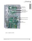
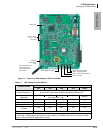
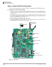
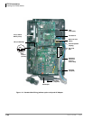
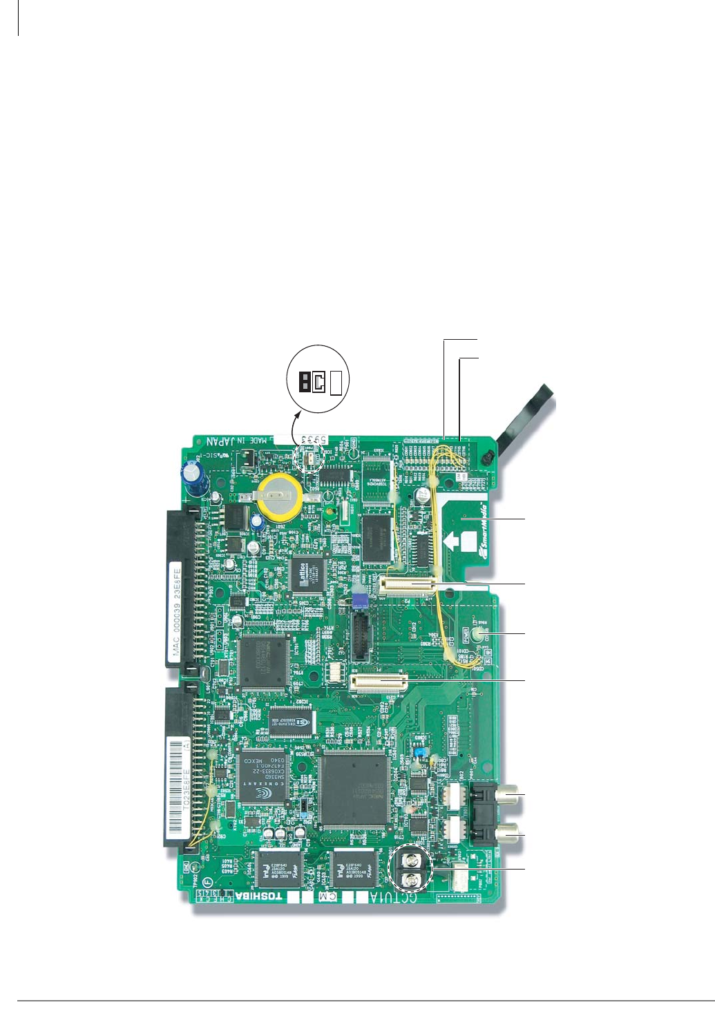
Figure 1-10 GCTU PCB
7264
OFF ON
BATT
P601 Battery
P903P902
SmartMedia Slot
DC Power On/Off LED
MOH
External Speaker
P2 (for BSIS)
P1 (for GETS)
P901
Control Relay Contact
SmartMedia LED
Heart Beat LED