


Peripheral Installation
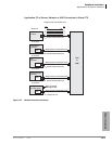
Application PC and Server Interfaces
Strata CTX I&M 06/04 12-5
Peripheral Installation
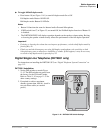
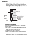
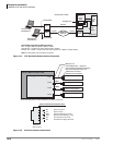
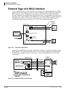
Figure 12-4 Network Interface Jack Pin Numbers and LEDs
5594
CD801
CD101
Network
Interface
RJ45
P7
TX
RX
LINK LAN Link Indication, LED On when Link is Connected
LAN Data Receive Indication, LED On when CTX is
Receiving Data Packets
LAN Data Send Indication, LED On when CTX is
Sending Data Packets
P5
5499
Strata CTX uses Pairs 2 and 3.
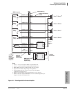
RJ45 Modular
Male Plug
1
2
3
4
5
6
7
8
1
2
3
4
5
6
7
8
P4
Pair 1
Pair 2
Pair 3
Pair 4
(8)
(7)
RD-
(5)
(4)
(6)
(3)
(2)
(1)
RD+
TD-
TD+
(not used)
(not used)
(not used)
(not used)
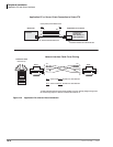
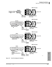
RJ45
( 8-pin jack )
TD-
TD+
Not Used
RD+
RD-
Not Used
Not Used
Not Used
2
1
4
3
6
5
8
7
CTX Network Interface Jack (P7)
TIA Network Wall Jack Wire Color Codes
CAUTION: Do not mix different TIA Wall Jack Types in an Installation.
Pair 2
Pair 3
Pin 1
Pin 2
Pin 3
Pin 6
Green
Green/White
Orange/White
Orange
TIA-568A
White/Green
Green/White
Orange/White
White/Orange
TIA-568B
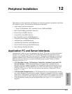
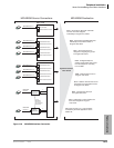
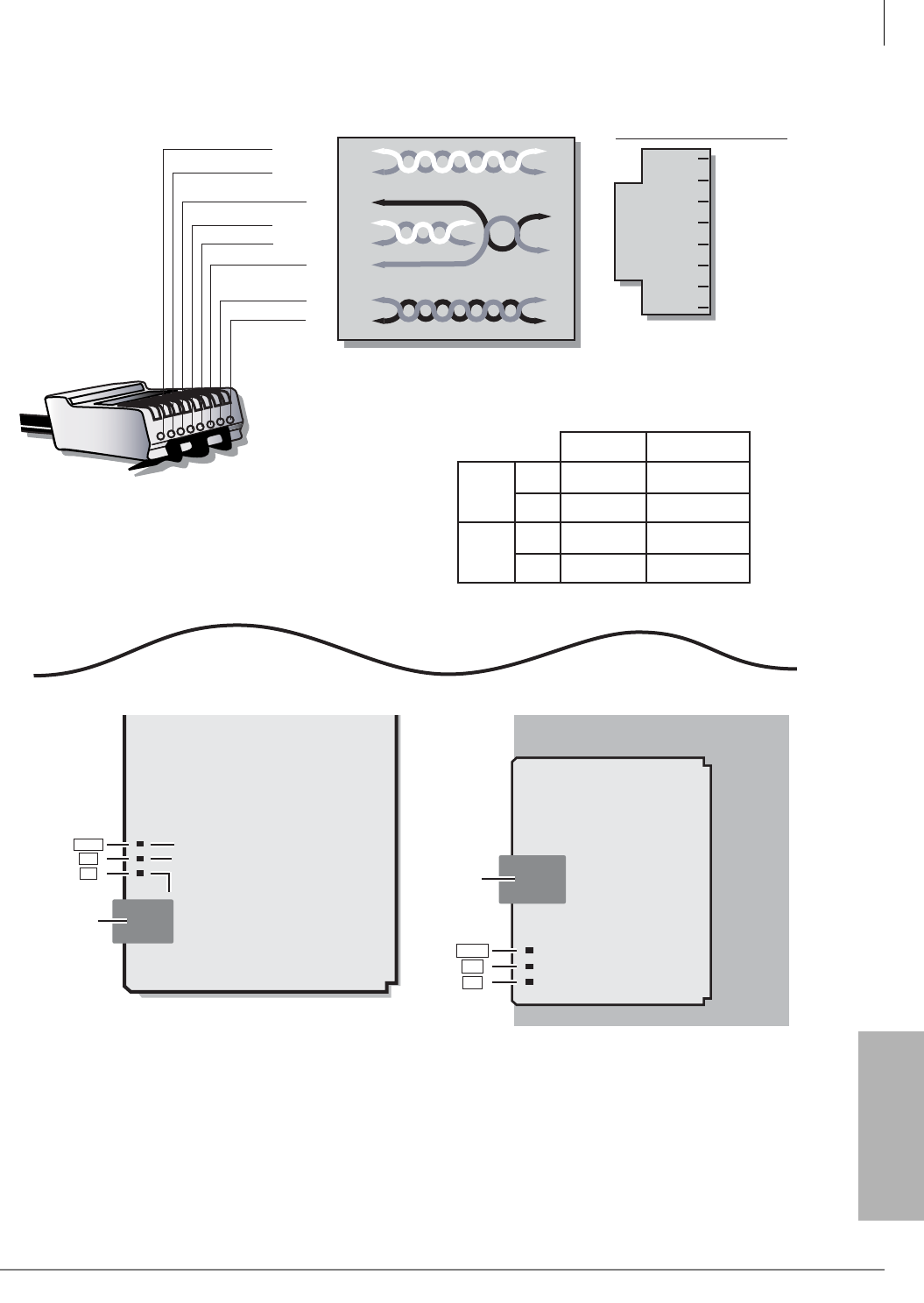
Network
Interface
RJ45
P1
TX
RX
LINK
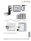
CTX100 ACTU1A
AETS
CTX 670 BBCU1A