


Peripheral Installation
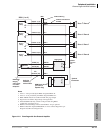
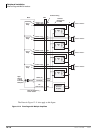
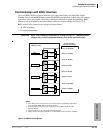
Door Phone/Door Lock with DDCB Interface
Strata CTX I&M 06/04 12-15
Peripheral Installation
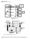
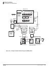
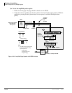
Calling from a Door Phone
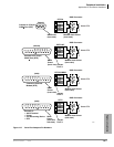
Each door phone has a push button that rings selected telephones with one of three unique bing-
bong sounds. The door phone’s location displays on ringing telephone LCDs. The three bing-bong
ring types are permanently assigned to each of the DDCB ports (A, B and C) as shown in Figure
12-16. Door phones can also be programmed to ring over the system’s external paging equipment.
When a telephone answers a door phone call, a two-way talk-path is established between the
calling door phone and the called telephone.
Calling a Door Phone
Each door phone has a unique number (#15XX, where “XX” = 01~24 max., depending on system
size) that can be dialed from system telephones. When a system telephone calls a door phone, the
door phone does not ring but provides a two-way talk-path between the calling telephone and the
called door phone. This enables telephone users to monitor sounds in the general area where the
door phone is installed.
Door Lock Control
As an option, Port B of the DDCB can be connected to a door lock control device, instead of a
door phone, to unlock a door. The door lock control device is not supplied by Toshiba and must be
ordered separately. The door lock option is a hardware jumper located on the DDCB. This option
provides relay contacts that will open, or close the Port B wire pair when a telephone’s door lock
button is pressed or when a door lock feature code is dialed from a telephone (see Figure 12-16 for
option settings).
Door Phone/Lock Programming
Door phone assignments are in Program 507 and door lock assignments are in Program 508.
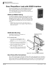
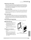
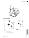
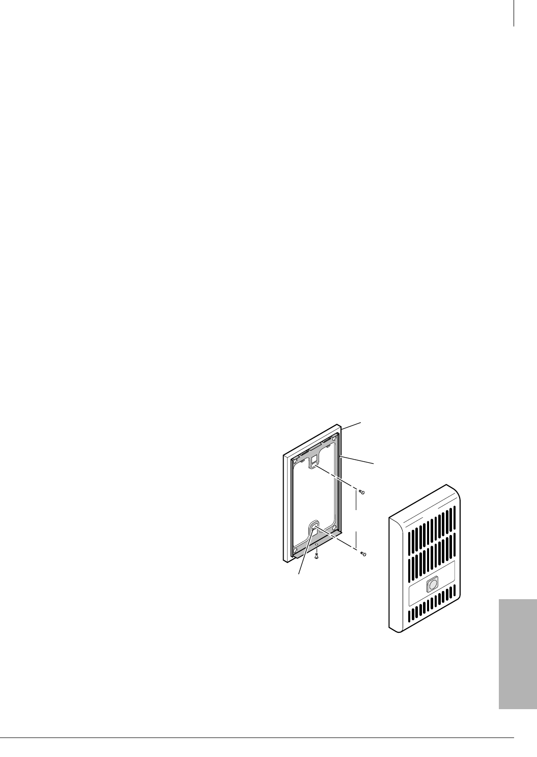
MDFB Wall Mounting
1. Remove the screw from the bottom of the
cover. Detach the cover from the base and
metal frame (see Figure 12-15).
2. Position the metal frame and base to the
mounting surface and secure with two one-
inch panhead wood screws.
3. Attach cover to the metal frame and base and
secure with the screw which was removed in
Step 1.
MDFB Volume Control Adjustments
1. Remove the screw from the bottom of the
MDFB cover.
2. Detach the cover from the base and metal
frame.
3. The volume level is changed by a screw
adjustment on the back of the MDFB. Turn
the screw with a flat-headed screwdriver
while ringing the MDFB or while on a call
with it. The volume level will change as the
screw is turned.
Two Wall
Mounting Holes
Door Phone
Base
Metal Frame
3.25
inches
1494
Figure 12-15 Door Phone (MDFB) Installation