


T1
RDTU Installation
8-4 Strata CTX I&M 06/04
RDTU Installation
³ To install an RDTU PCB
1. Set the jumper wire plugs to the correct position for the cable length.
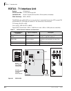
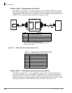
• RDTU3 – see “RDTU3 - T1 Interface Unit” on page 8-2
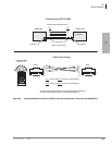
• RDTU1 and 2– see “RDTU3 Cabling” on page 8-5.
2. Turn the Strata CTX system power Off.
3. Refer to Chapter 2 – Strata CTX Configuration to determine the appropriate slot for the RDTU:
• “Worksheet 5: Strata CTX100 Cabinet Slots” on page 2-26
• “Worksheet 6: Strata CTX670 Cabinet Slots” on page 2-37
• “RDTU3 - T1 Interface Unit” on page 8-2 or “RDTU3 Cabling” on page 8-5
4. Insert the RDTU (component side facing right) into the appropriate slot and apply firm, even
pressure to ensure proper seating of connectors.
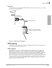
5. For the RDTU3 only, set the SW10 jumper plug for internal or external ROM operation, per
Table 8-3.
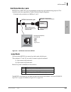
Note For cabling information and requirements, refer to the specific instructions for the type of
card.
Power Factor
RDTU3A uses 5V only. 5V power factor = 2.0, -24PF = 0.0
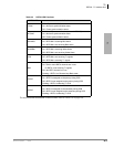
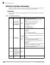
Table 8-3 SW10 Internal or External ROM Setting
Mode SW10 Note
Internal ROM
(Default mode)
CPU
When there is an internal ROM on the CPU (TMP93PW46), RDTU3A
operates with the SW10.
Use this mode when IC19 is not on PCB (see Figure 8-1).
If the SW10 is in CPU position, RDTU3A is operating with the internal
ROM regardless of IC19 existence.
External ROM
(Upgrade)
ROM
RDTU3A is operating with the external ROM (IC19).
Use this mode only when IC19 is on PCB (see Figure 8-1).
If the SW10 is in ROM position without IC19, the RDTU3A will not work.