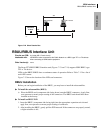
CTX28 Installation
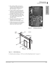
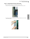
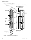
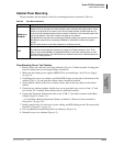
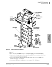
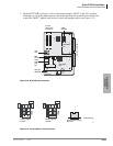
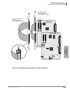
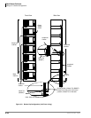
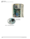
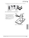
Installing the CTX28 Cabinet
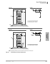
Strata CTX I&M 06/04 1-13
CTX28 Installation
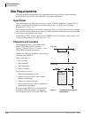
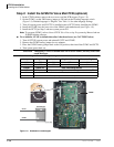
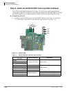
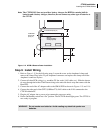
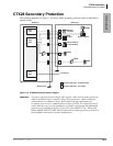
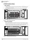
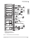
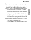
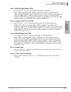
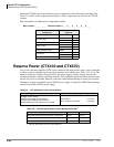
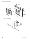
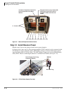
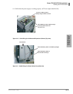
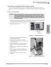
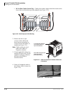
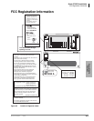
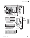
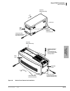
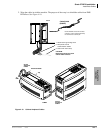
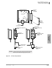
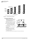
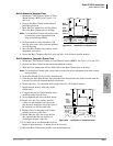
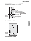
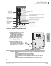
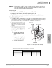
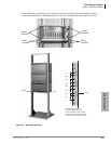
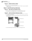
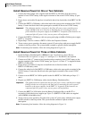
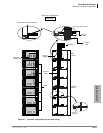
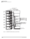
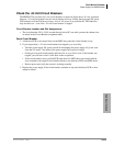
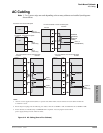
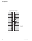
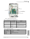
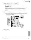
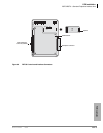
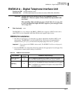
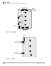
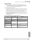
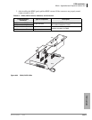
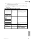
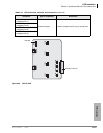
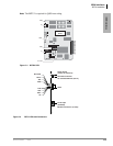
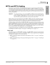
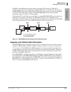
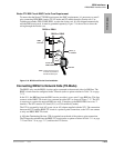
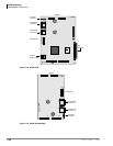
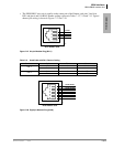
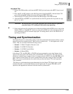
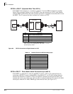
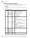
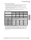
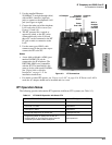
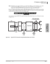
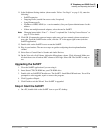
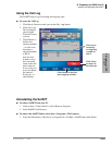
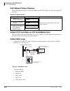
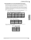
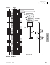
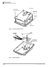
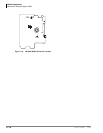
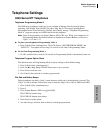
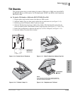
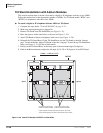
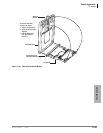
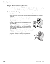
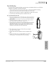
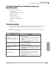
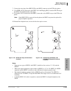
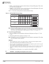
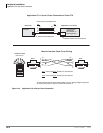
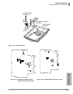
Figure 1-9 Close Up of PCB Stopper for GCTU and GVMU
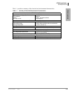
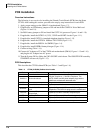
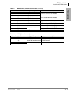
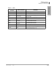
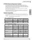
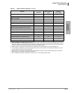
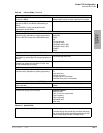
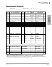
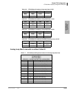
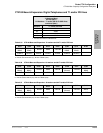
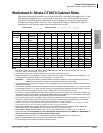
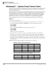
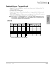
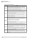
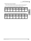
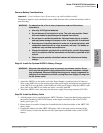
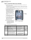
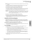
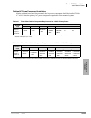
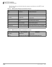
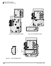
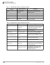
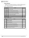
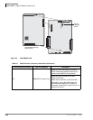
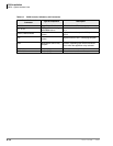
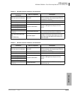
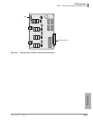
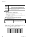
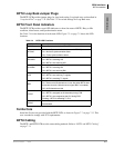
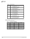
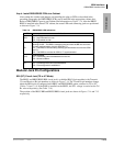
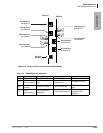
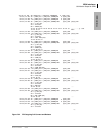
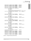
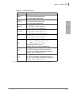
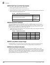
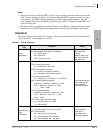
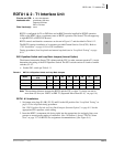
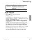
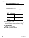
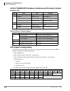
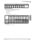
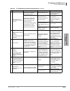
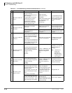
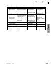
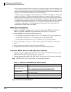
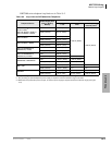
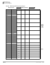
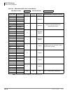
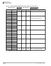
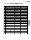
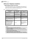
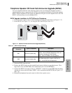
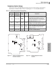
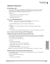
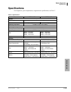
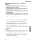
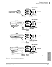
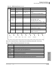
Table 1-7 LED Indicators on the GVMU1A
Indication/ State
GVMU1A LEDs
Ch1 Ch2 Ch3 Ch4 Status
Power On
(Initialize Sequence*)
All LEDs turn ON (Red), then all LEDs turn OFF and cycle ON/OFF through all ports
for one to two minutes while initializing and then all LEDs turn off.
Normal
(Busy/Idle)
OFF OFF OFF OFF
Blinking
ON = Busy; OFF = Idle
Failure Blinking Blinking Blinking Blinking OFF
Shut Down ON ON ON ON OFF
Back Up/Restore ON ON ON ON ON
No 1.8V input Voltage
in GVMU
ON OFF OFF ON ON
Not mounted/defective Light flickers and switches from the LED to LED (from Ch1~Ch4) + Status LED
* The initialize sequence operates each time the CTX28 power is cycled off/on or the CTX28 processor is reset
or initialized – GVMU program data remains saved. However, if the GVMU battery jumper is removed, GVMU
program data and saved messages will be erased.
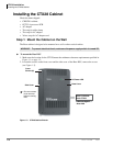
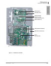
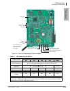
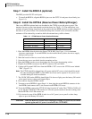
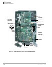
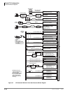
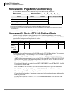
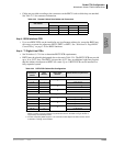
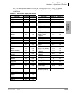
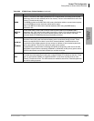
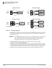
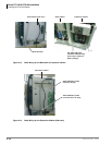
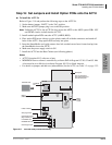
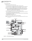
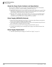
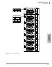
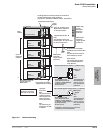
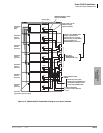
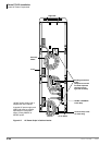
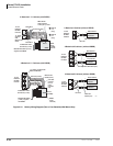
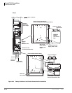
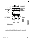
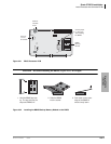
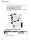
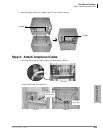
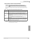
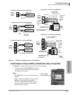
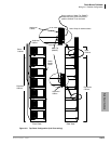
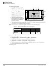
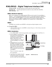
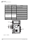
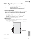
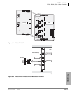
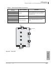
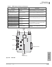
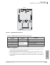
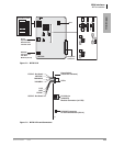
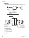
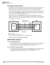
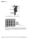
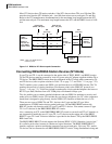
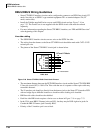
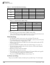
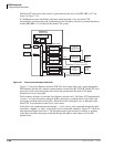
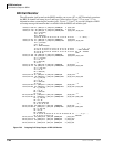
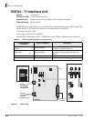
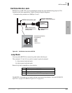
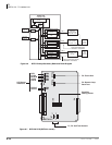
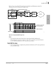
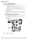
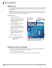
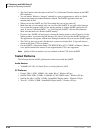
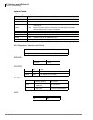
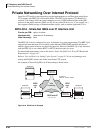
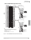
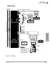
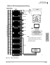
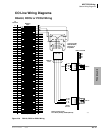
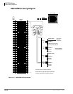
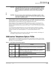
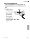
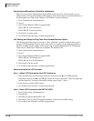
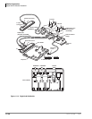
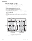
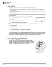
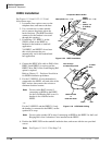
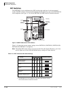
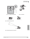
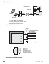
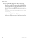
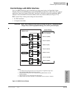
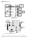
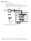
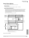
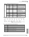
7395
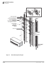
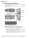
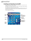
SW2 - Language Jumper
SW6 - Battery Jumper
RS232C
Maintenance
Jack
Status LED
VM Port LEDS
(Ch1 ~ Ch4)
Busy/Idle
SW3 - Language Jumper
SW4 - Admin PC/Debug Monit
SW5 - Not Used
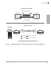
Note: For details, see
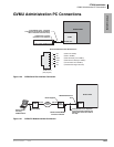
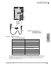
GVMU Admin PC
Connections later in
this chapter.