


Strata CTX100-S/CTX100 Installation
Installing the CTX100 Cabinet
Strata CTX I&M 06/04 3-19
Strata CTX100-S/
CTX100 Installation
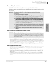
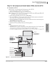
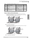
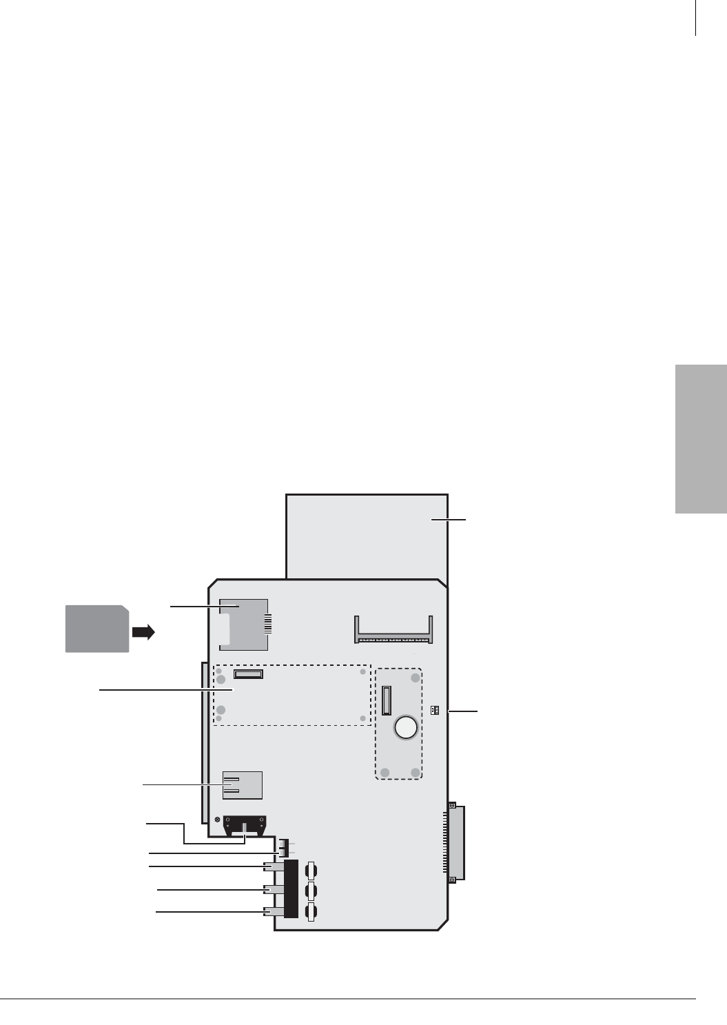
Step 16: Set Jumpers and Install Option PCBs onto the ACTU
³ To install the ACTU2A
Refer to Figure 3-18 and perform the following steps on the ACTU2A.
1. Set the battery jumper, “BATT,” to the “On” position.
2. Make sure the WDT jumper plug is set to the ON position.
Note Unlike the ACTU1A, the ACTU2A does not use the AETS or the ARCS option PCBs. NIC
and DTMF circuits are built into the ACTU2.
3. Install needed option PCBs onto the ACTU (AMDS, BSIS).
4. Place option PCB arrow side up over the plastic stand-offs with the connectors and stand-off
holes on the ACTU. Snap option PCB securely into place.
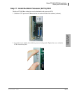
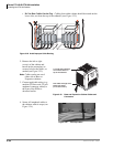
5. Insert the SmartMedia card (gold contacts face left, notched corner faces forward and up) into
the SmartMedia slot on the ACTU.
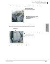
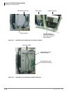
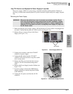
6. Make sure the power supply switch is Off.
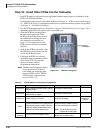
7. Install the ACTU into the Base Cabinet (see following photos).
Notes
• ACTU2A requires R1.3 software or later.
• MOH/BGM source volume is controlled by software PAD in Program 107-01, 02 and 03. Mu/
A law must be set to Mu law in software Program 105-35 for North America.
• For details on jumpers and add-ons (subassemblies) for the ACTU, see Table 3-2 on page 3-22.
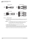
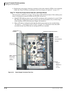
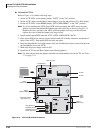
Figure 3-17 ACTU2A PCB (CTX100 Processor)
600/600600/600 600/600
ON
P601
OFF
BATT
MOH1 EX SPMOH2
P2
P4
ACTU2
P3
R806
P6
P5
Place
BSIS
here
Place
AMDS
here
6636
BSIS1A
(RS232-C, SMDR and SMDI)
Control Relay Terminal
(Night Transfer, etc.)
ASTU plugs into P3
MOH/BGM1 RCA Jack
600 ohm page output
Metal Spacer
Future MOH2 Jack
10 Base-T Ethernet
Battery
Backup
Jumper
SmartMedia
Slot
SmartMedia Card
Note: The ACTU1A is a
larger board and does not
have the metal spacer.