


PCB Installation
RMCU/RCMS – E911 CAMA Trunk Direct Interface
6-38 Strata CTX I&M 06/04
RMCU/RCMS – E911 CAMA Trunk Direct Interface
Circuits per PCB:
four circuits
Interfaces with:
enhanced 911 locator services
Older Version(s):
none
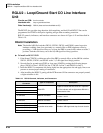
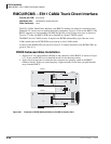
The E911 CAMA Trunk Direct Interface card (RMCU) enables cost-effective connection to the
Enhanced 911 locator services without third-party equipment. Figure 6-29 shows the RMCU. The
RMCU supports two subassemblies (RCMS) that provide a total of up to four ports as shown in
Figure 6-27. Only one RMCU PCB can be installed in a Strata CTX670 system.
The RMCU has no CAMA circuits. It requires one RCMS subassembly to provide one or two
CAMA trunks and two RCMS PCBs to provide up to four CAMA trunks.
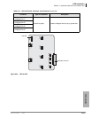
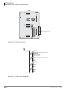
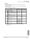
Location of the RCMS LEDs are shown in Figure 6-30 and the functions of the RCMS LEDs are
given in Table 6-19.
RCMS Subassemblies Installation
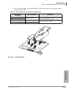
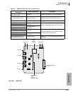
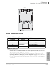
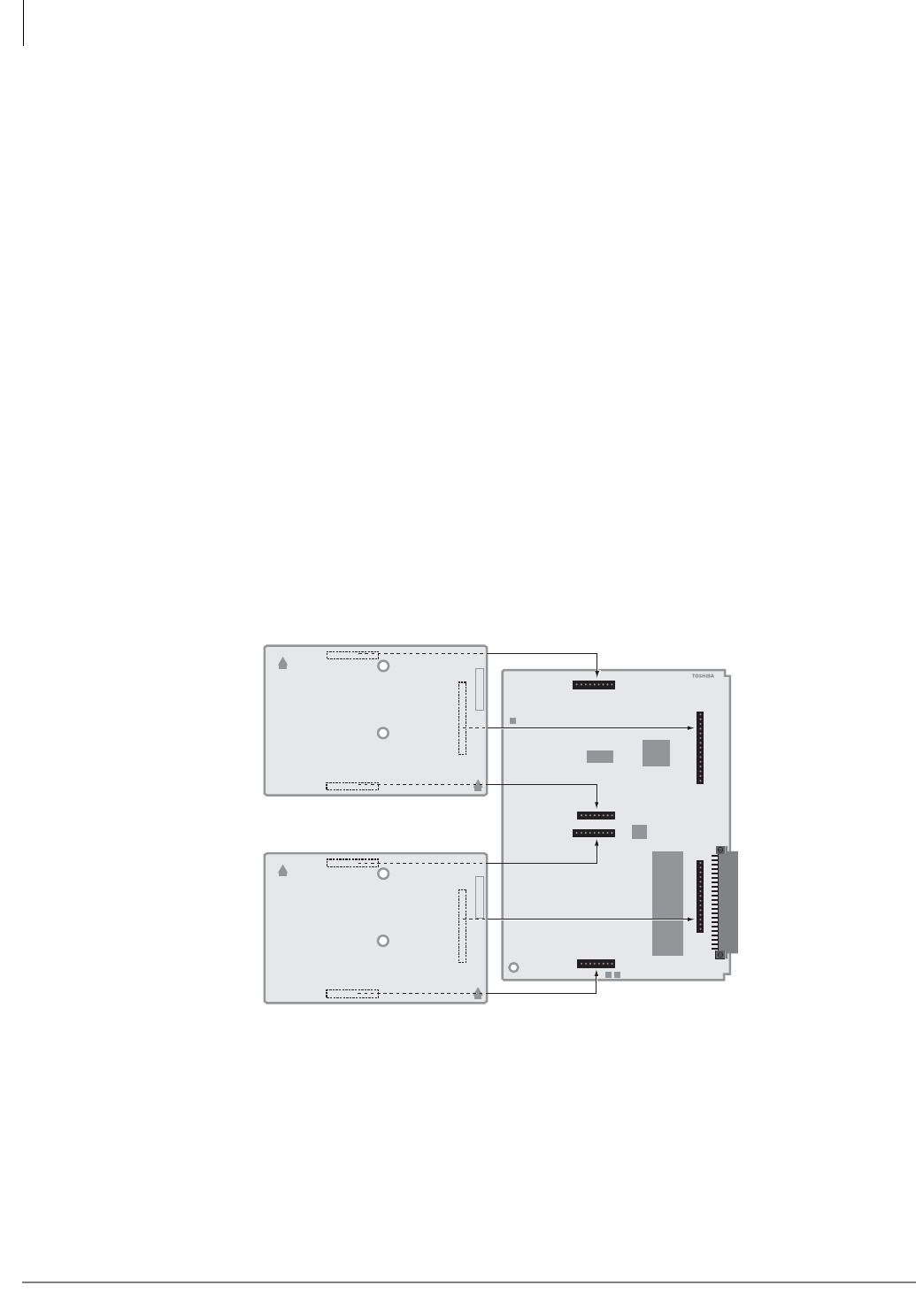
1. Attach one or two subassemblies (RCMS) to the connectors on the RMCU as shown in Figure
6-27. If only one RCMS is to be installed, install it in the bottom position.
2. Apply firm even pressure to ensure that the connectors are properly seated in the RMCU
connector blocks. If they are seated properly, a light resistance is felt when you pull the units
away from the RMCU.
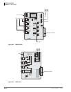
Figure 6-27 Placement of RCMS Subassemblies on the RMCU Interface Card
RMCU1A -CM V.1
RMCU1A
2758
UP
®
UP
ABCDEFGHK
RCMS1A
RMCU1A
UP
®
UP
ABCDEFGHK
RCMS1A
P6
P5
P7
P3
P2
P4