Strata CTX100-S/CTX100 Installation
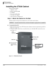
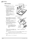
Installing the CTX100 Cabinet
Strata CTX I&M 06/04 3-23
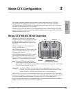
Strata CTX100-S/
CTX100 Installation
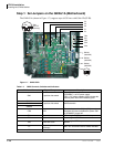
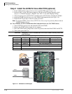
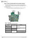
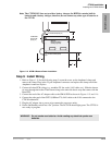
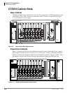
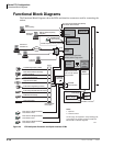
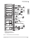
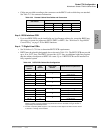
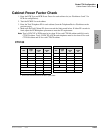
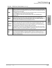
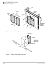
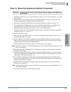
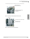
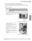
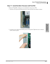
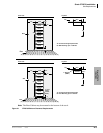
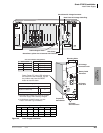
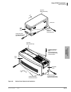
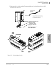
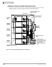
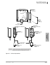
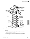
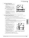
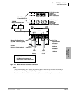
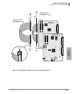
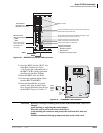
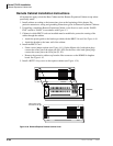
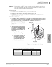
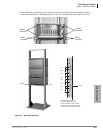
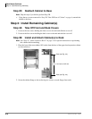
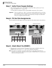
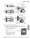
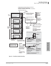
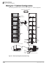
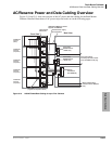
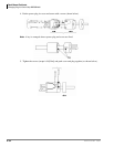
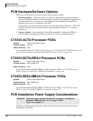
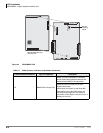
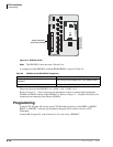
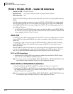
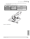
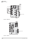
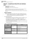
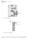
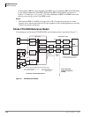
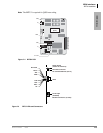
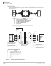
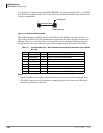
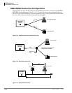
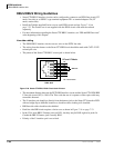
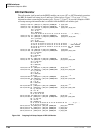
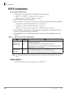
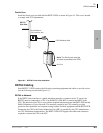
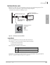
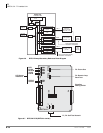
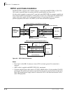
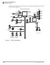
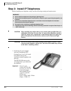
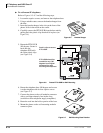
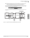
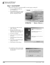
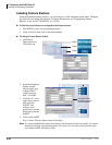
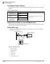
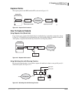
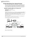
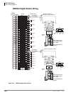
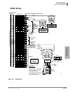
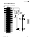
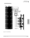
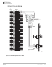
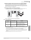
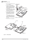
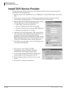
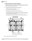
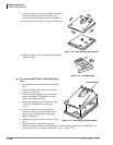
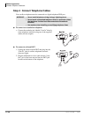
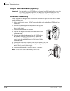
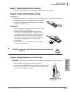
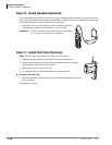
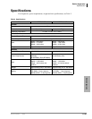
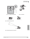
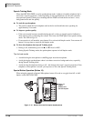
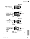
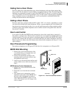
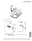
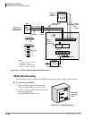
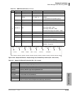
Step 19: Attach and Route PCB Cables
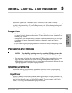
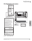
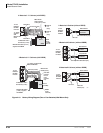
1. Determine the direction that you want the cables to exit the cabinet(s) from the following:
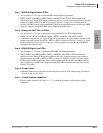
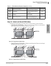
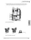
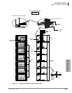
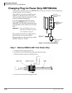
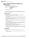
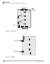
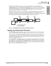
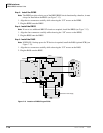
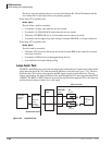
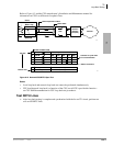
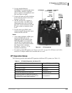
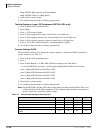
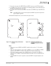
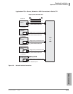
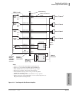
• Single Direction Cable Routing – Cabling from the Expansion Cabinet can run through the
Base Cabinet and exit from the Base Cabinet (see Figure 3-20).
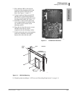
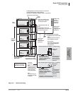
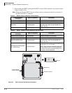
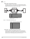
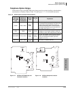
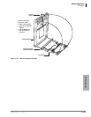
Figure 3-20 Single Direction Cable Routing
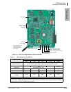
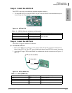
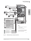
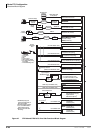
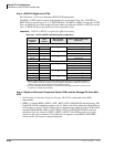
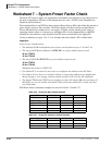
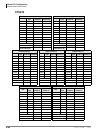
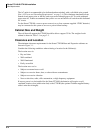
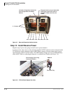
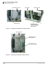
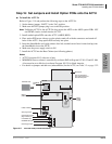
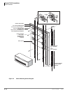
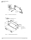
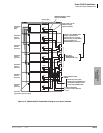
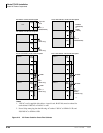
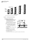
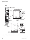
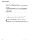
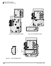
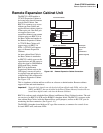
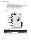
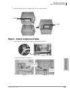
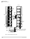
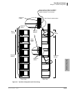
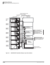
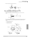
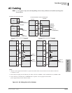
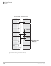
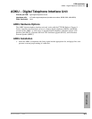
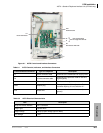
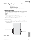
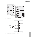
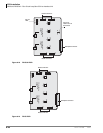
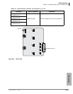
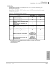
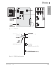
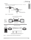
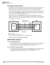
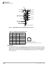
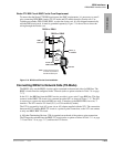
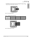
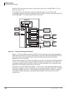
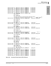
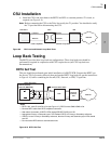
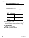
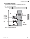
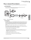
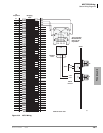
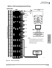
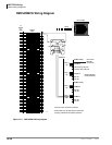
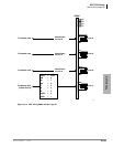
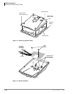
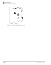
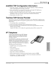
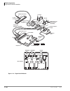
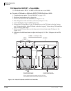
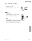
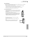
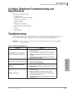
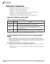
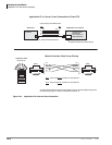
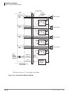
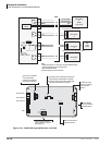
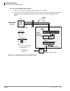
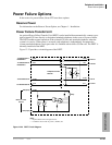
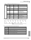
• Opposite Direction Cable Routing – Cabling from the Expansion Cabinet can run through
the right and left sides (see Figure 3-21).
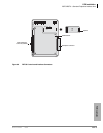
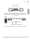
Figure 3-21 Opposite Direction Cable Routing
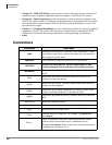
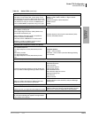
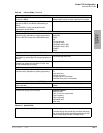
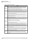
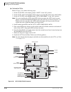
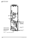
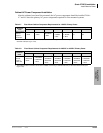
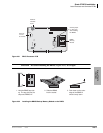
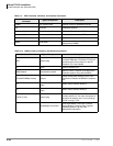
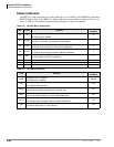
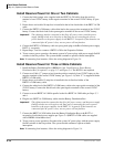
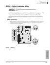
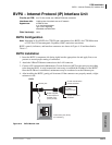
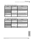
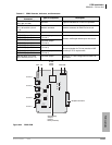
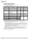
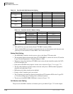
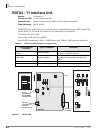
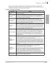
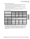
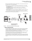
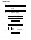
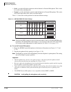
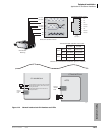
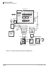
AETS
(Optional)
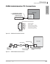
Ethernet LAN (10 BaseT)
One per system. Provides 10Mbps
LAN by one RJ45 for WinAdmin.
ACTU1 only
AMDS
(Optional)
V.34 Modem
One per system to provide
33.6kbps maximum modem for
WinAdmin.
ACTU
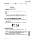
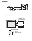
BSIS
(Optional)
Serial interface unit (same unit used for
CTX670).
Provides four RS-232 serial ports
(SMDR, SMDI)
ACTU
ABCS
(Optional)
Battery Charger Circuit.
One per Power Supply for
connection of Reserve Power
(requires ABTC-3M Battery Cable).
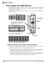
APSU112A
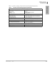
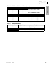
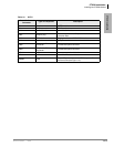
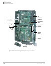
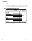
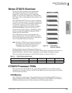
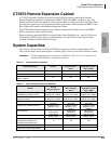
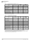
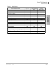
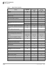
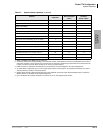
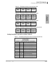
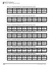
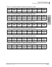
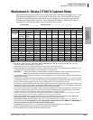
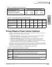
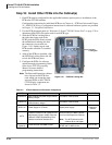
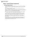
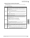
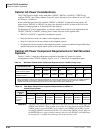
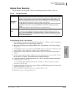
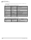
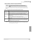
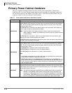
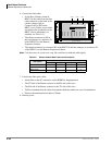
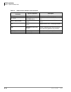
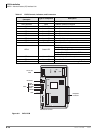
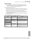
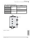
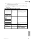
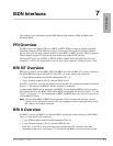
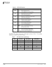
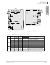
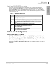
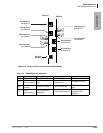
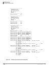
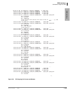
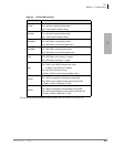
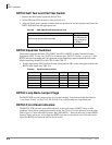
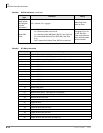
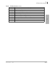
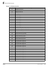
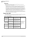
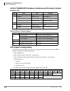
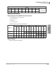
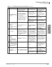
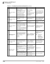
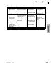
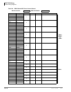
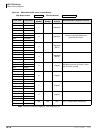
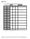
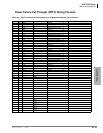
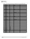
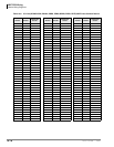
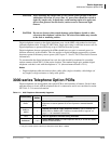
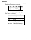
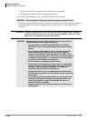
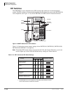
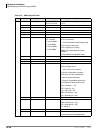
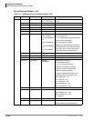
Table 3-2 CTX100 Cabinet and Processor Components
(continued)
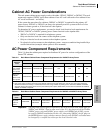
PCB Provides Comments Installs On
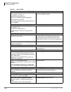
6006
Power SupplyPower Supply
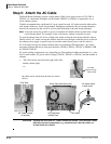
AC Cord and
Battery Cables
6007
Power SupplyPower Supply
AC Cord and
Battery Cables