


Station Apparatus
2000-series Telephones
11-48 Strata CTX I&M 06/04
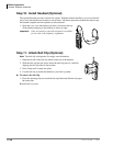
HHEU Installation
See Figures 11-24 and 11-32~11-35 and
follow these steps:
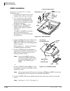
1. Loosen the four captive screws on the
telephone base, and remove the base.
2. Use a screwdriver or other suitable
tool to remove the plastic tab on the
back of the base. (The HHEU modular
connector for the headset is accessed
through this opening.)
3. If installing a V.3 HHEU1, set the
SW601 switch on the HHEU to
headset for the headset or loud bell
application.
V.4 HHEU1 and HHEU2 do not have
this switch, because they are
automatically set for the headset/loud
bell application.
4. Connect the HESC-65A cable to P601 of the
HHEU (both HHEU1A versions and the
HHEU2 have P601) if the Loud Ringing Bell
option is required.
Refer to Chapter 12 – Peripheral Installation
for HESB installation procedures.
5. For the V.3 HHEU1: If only the headset is
connected to the HHEU, cut both sides of the
R607 resistor, then remove the resistor to
eliminate electrical contact.
Note Do not cut the R607 resistor if
connecting an HESB to the HHEU
for the Loud Ringing Bell–even if a
headset is also installed on the
HHEU.
...or
For the V.4 HHEU1 and the HHEU2: if only
the headset is connected to the HHEU, cut the
speaker OCA strap.
Note Do not cut the speaker OCA strap if connecting an HESB to the HHEU for the Loud
Ringing Bell–even if a headset is also installed on the HHEU.
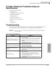
6. Position the HHEU PCB on the standoffs inside the base, and secure with the two provided
screws.
Note See Figures 11-34~11-35 for Steps 7~8.
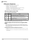
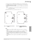
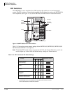
HHEU
Component Side of HHEU
SW601
(HHEU1 V.1 ~ V.3)
P601
R607 (HHEU1 V.1 ~ V.3)
OCA
(HHEU1 V.4
or HHEU2)
1487
Figure 11-32 HHEU Installation
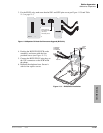
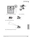
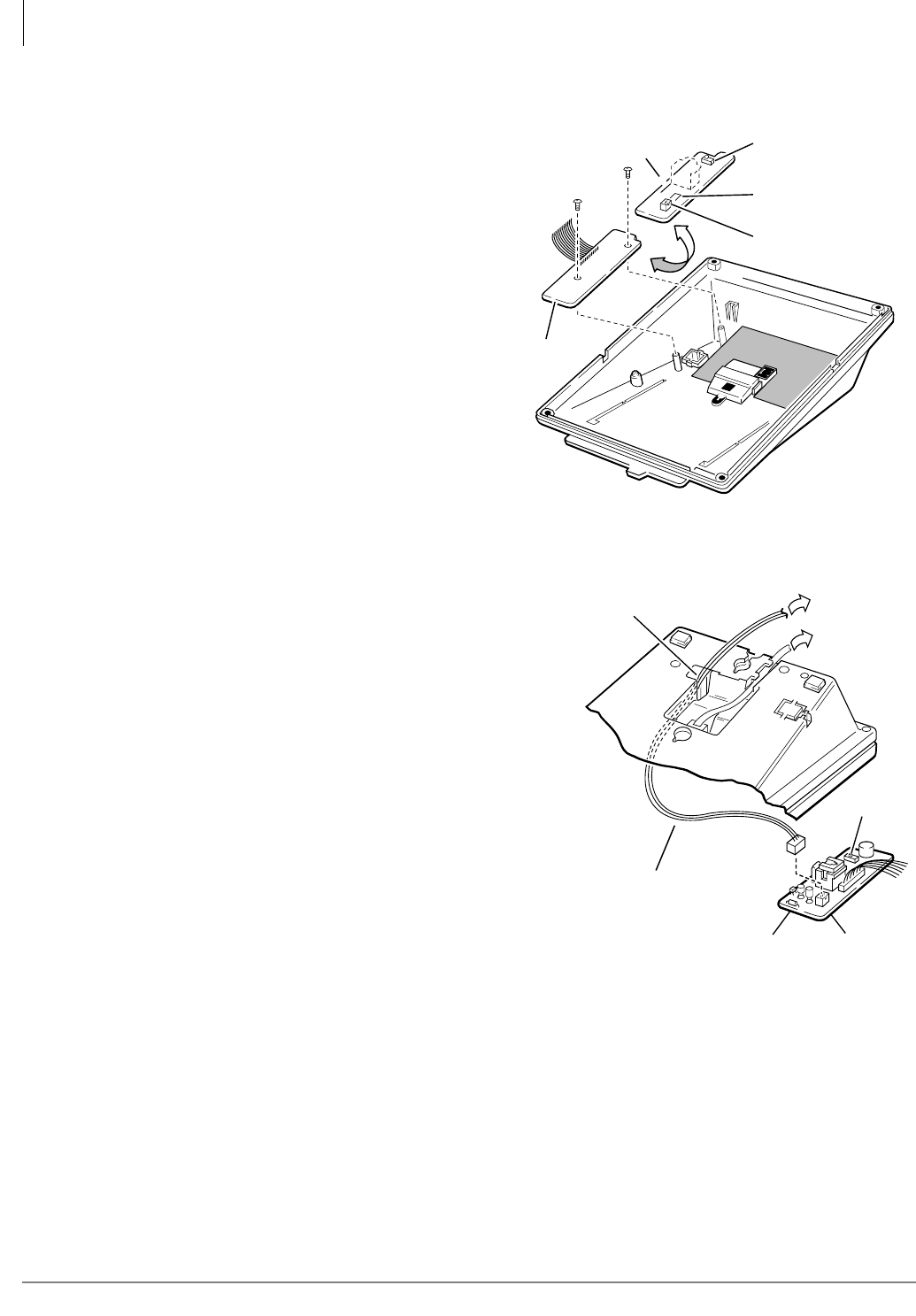
Feed Through
for HESC-65(A) Cable
To HESB
Block
SW601
HHEU
P601
HESC-65 Cable
or
HESC-65A Cable
1488
Figure 11-33 HESC-65A Cabling