Strata CTX100-S/CTX100 Installation
Installing the CTX100 Cabinet
3-22 Strata CTX I&M 06/04
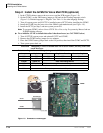
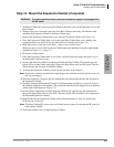
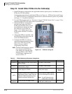
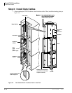
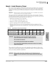
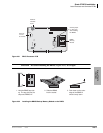
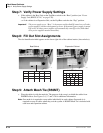
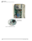
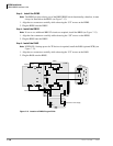
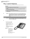
Step 18: Install Other PCBs into the Cabinet(s)
1. Each PCB must be configured for the applicable hardware options prior to installation of the
PCB to the CTX100 cabinets.
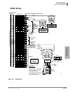
Configuration instructions for individual PCBs are in Chapter 6 – PCB Installation and Chapter
10 – MDF PCB Wiring. Configuration instructions for external hardware options are provided
in Chapter 12 – Peripheral Installation.
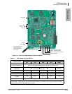
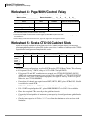
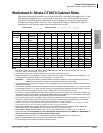
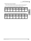
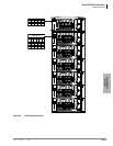
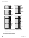
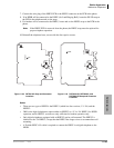
2. Use the PCB placement guide in “Worksheet 5: Strata CTX100 Cabinet Slots” on page 2-26 to
determine which PCB slot can be used for each PCB type.
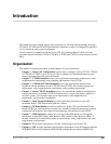
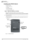
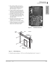
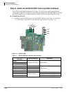
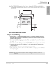
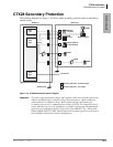
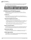
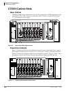
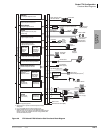
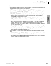
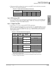
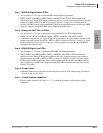
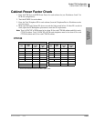
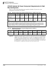
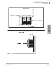
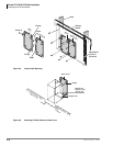
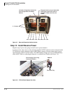
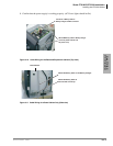
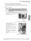
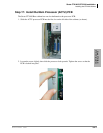
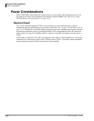
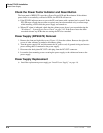
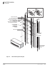
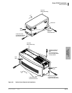
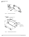
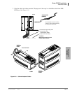
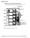
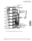
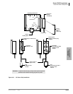
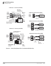
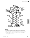
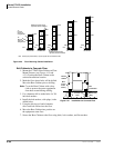
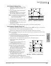
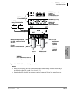
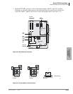
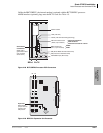
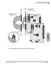
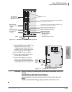
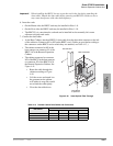
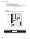
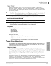
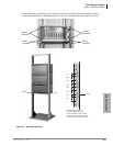
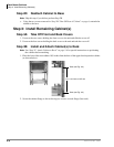
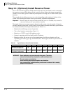
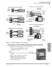
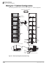
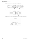
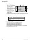
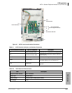
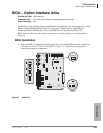
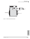
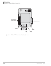
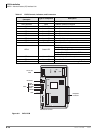
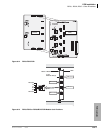
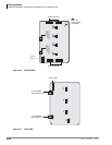
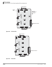
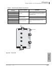
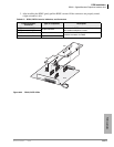
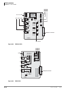
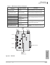
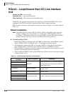
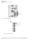
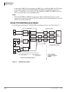
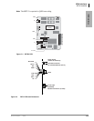
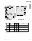
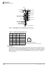
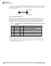
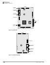
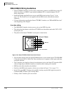
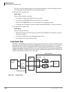
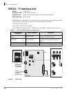
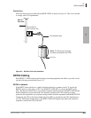
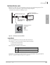
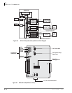
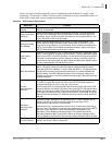
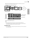
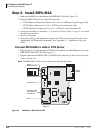
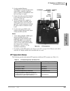
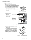
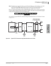
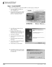
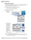
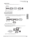
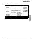
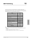
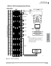
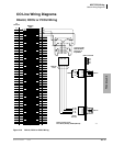
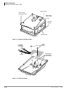
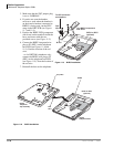
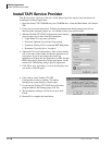
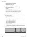
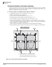
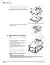
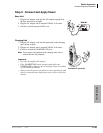
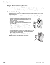
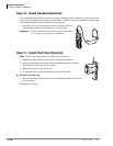
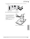
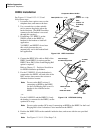
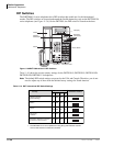
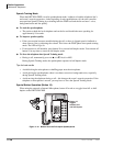
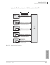
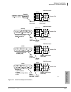
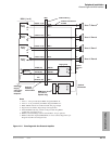
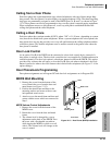
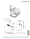
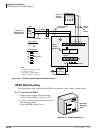
3. Slide the PCB Slot Locking Bar to
the right, then insert each of the
PCBs; push the PCBs firmly toward
the motherboard, making sure that
the connectors are secured (see
Figure 3-19). Lightly tug on each
PCB to make sure that it’s installed
securely.
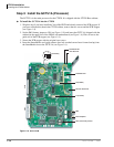
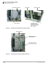
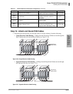
4. After all the PCBs are installed, slide
the PCB Slot Locking Bar to the left
to lock the PCBs into place.
5. Configure the PCBs for software
options through programming. Refer
to the Strata CTX Programming
Manual for more detailed
programming instructions.
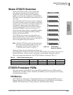
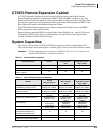
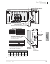
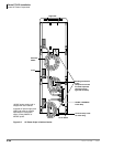
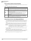
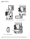
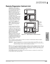
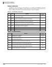
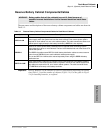
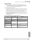
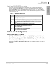
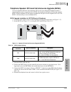
Note The Base and Expansion cabinets
have four universal PCB slots
each which can accept the same
universal PCBs as the CTX670.
CTX100-only components are
shown in Table 3-2.
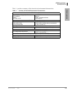
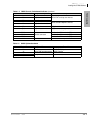
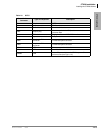
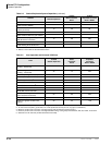
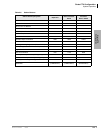
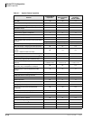
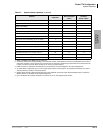
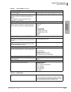
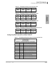
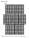
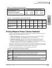
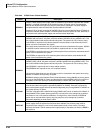
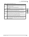
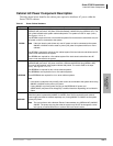
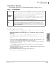
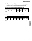
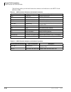
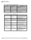
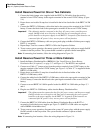
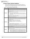
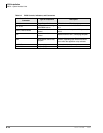
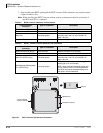
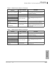
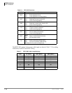
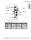
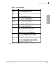
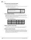
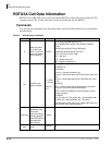
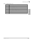
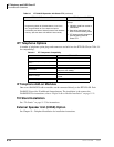
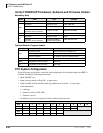
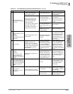
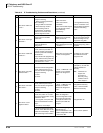
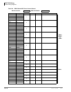
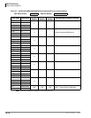
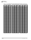
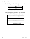
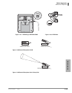
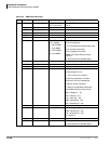
Table 3-2 CTX100 Cabinet and Processor Components
PCB Provides Comments Installs On
CHSUB112
Base Cabinet with power supply without
battery charger.
Provides 4 universal slots.
CHSUE112
Expansion Cabinet with power supply
without battery charger.
Provides 4 universal slots.
APSU112 Power Supply for CTX100. Spare power supply.
Base or
Expansion
Cabinet
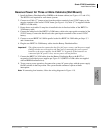
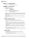
ACTU
System Processor PCB. (Optional PCB
attachments include: modem. Ethernet
10BaseT, DTMF Receiver/Busy Tone
Detector and Serial Interface Unit.
One per system. Supports 8 PCB
slots (4 slots in the Base Cabinet +
4 more in the Expansion Cabinet).
Note The ACTU2A works with
software R1.3 and higher.
ARCS
(Optional)
DTMF Receiver and ABR Circuits.
One per system. Provides 16
DTMF and 16 ABR circuits.
ACTU1 only
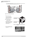
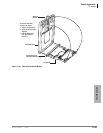
PCB Slot
Locking Bar
6005
Figure 3-19 PCB Slot Locking Bar